
External Event Camera Synchronization#
Overview#
The FRAMOS Industrial Depth Camera D400e Series - External Event Camera Synchronization application note provides general recommendations on how to synchronize the FRAMOS D400e camera series to an external event.
Synchronous streams to an external event can be achieved by:
Hardware: utilizing the camera’s external synchronization interface
Software: sending the software trigger command
Additionally, the cameras need to be configured via the software interface to work in such an environment.
Note
All the information given in this application note is valid for the FRAMOS D400e camera series firmware version v1.11.0.0 (or higher) for D435e, v1.6.0.0 (or higher) for D415e and v1.5.0.0 (or higher) for D455e. The required D400e software package version is v2.1.0 (or higher) for D435e and D415e, and v2.8.0 (or higher) for D455e.
Functional Description#
By default, the FRAMOS D400e camera series is in “Default Mode”, streaming at the requested frame rate. When operating in “Master Mode” (refer to the FRAMOS Industrial Depth Camera D400e Series - Multi-Camera Synchronization appnote [Ref-2] for an explanation of operating modes), the camera outputs the synchronization signal on the Opto-isolated OUT (VSYNC) as shown in Fig. 1. The VSYNC signal is related only to the stereo sensor. The RGB sensor does not output the signal on the Opto-isolated OUT.
Figure 1 – Opto-isolated OUT in “Master Mode”, VSYNC, 30Hz#
2.1 External Event Operation#
In “External Event” operating mode, the camera works in continuous mode at the requested frame rate, but no frames are sent to the host. When an external pulse is applied on the synchronization interface or the software trigger command is sent, the camera sends the next frame generated to the host as shown in Fig. 2.
Figure 2 – External Event Operation#
As the external event is asynchronous to the internal camera sensor timing, there will be a variable delay between the input pulse (hardware or software) and the generated frame, as shown on Fig. 3, where SYNC PULSE is the external pulse applied to the camera, while VSYNC represents the start of the generated stereo frame that is sent to the host.
Figure 3 – SYNC PULSE, VSYNC#
This variable delay (frame jitter) will never exceed the 1 frame readout time. Maximum delays (TMAX) for various frame rates are given in Table 1.
FPS |
T MAX < 1/FPS |
|---|---|
60 Hz |
16.66 ms |
30 Hz |
33.33 ms |
15 Hz |
66.66 ms |
Table 1 – Maximum frame jitter for various frame rates
2.1.1 Software Trigger#
In “External Event” software trigger operating mode, stereo and RGB sensors work in continuous mode at the requested frame rate, with no frames sent to the host.
When the software trigger command is sent to either stereo or RGB, the camera sends the next frame generated to the host as shown in Fig 2.
The stereo sensor has an additional option “RS2_OPTION_SOFTWARE_TRIGGER_ALL_SENSORS” that specifies whether the trigger signal is forwarded to all sensors or is sent to only the stereo sensor.
When “RS2_OPTION_SOFTWARE_TRIGGER_ALL_SENSORS” is set to 1, the trigger signal is sent to all sensors and the camera sends the next frames generated to the host as shown in Fig. 4.
If “RS2_OPTION_SOFTWARE_TRIGGER_ALL_SENSORS” is set to 0, the software trigger signal is sent to the stereo sensor only and the camera sends the next stereo frame generated to the host as shown in Fig 4.
Figure 4 – Software trigger, RS2_OPTION_SOFTWARE_TRIGGER_ALL_SENSORS#
Note
The camera outputs the VSYNC signal only for the stereo sensor.
2.2 Genlock Operation#
Genlock functionality, introduced in the latest Intel D4 firmware, is available on depth cameras that are based on Global Shutter imagers. From FRAMOS D400e series, this feature is supported on D435e and D455e cameras.
With the Genlock feature, depth frames can be triggered at arbitrary times or frequencies. Basically, the Genlock feature can be related to a slave mode operation for machine vision cameras where the input trigger signal starts the exposure window on the image sensor.
Starting with firmware version 1.5.0.0, the D455e camera supports Genlock triggering for the color sensor. When both the color and the depth sensor are in Genlock mode, the frames are synced. More details on the feature are given in the External Synchronization of Intel® RealSense™ Depth cameras white paper [Ref-4].
As described in the “External event operation” chapter, there will be a variable delay between the input pulse (hardware or software) and the generated frame, as shown on Fig 3. For Genlock operation, delay between the input pulse and the generated frame is fixed and depends on the set exposure time, as shown on Fig. 5.
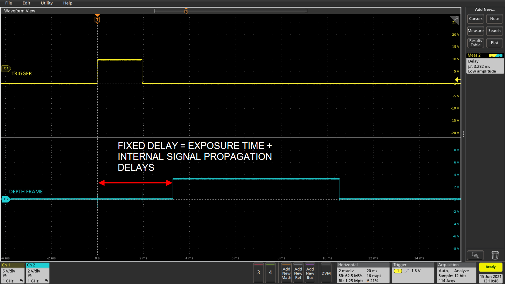
Figure 5 – SYNC PULSE, VSYNC for Genlock#
The internal signal propagation delay is an additional delay between the input pulse and the start of the exposure, as shown on Fig. 6. This delay varies for different stream profiles, as shown in Table 2.
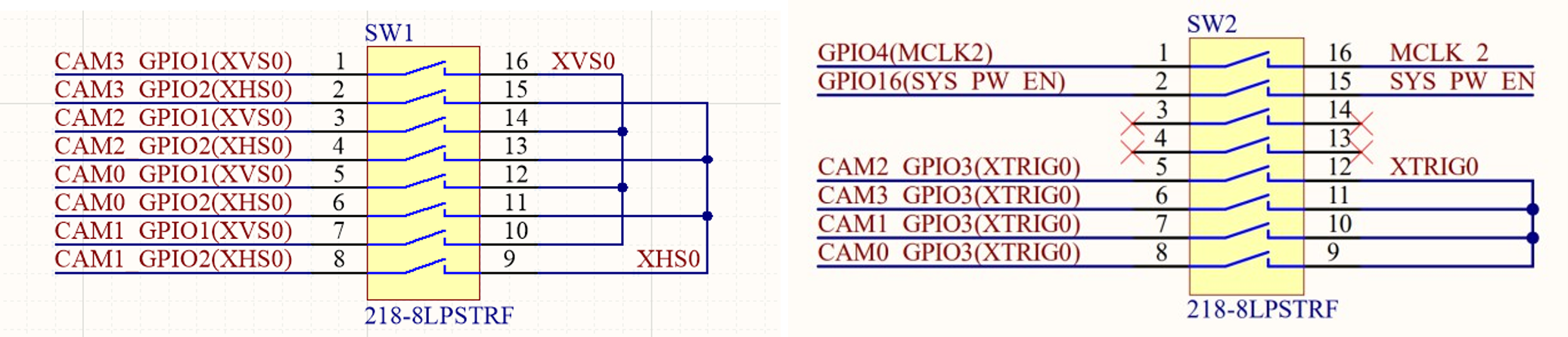
Figure 6 – Delay from Input Pulse to Start Of The Exposure#
Stream Profile |
T EXP_D [µs] |
T VSYNC_D [µs] |
|---|---|---|
1280x720 |
~880 |
~2.3 |
Others |
~790 |
~2.3 |
Table 2 – Delay from trigger to start of exposure for various stream profiles
Note
When operating in Genlock mode, VSYNC represents the start of the frame generation sequence (not start of exposure or start of readout, as shown on Fig. 6).
For other operating modes, VSYNC represents start of readout.
In addition, when using the Genlock feature, a burst of frames can be sent to the host using one trigger. The number of frames within one burst is limited to 255 frames. The color sensor frame burst number in Genlock mode is the same as the one set for the depth sensor.
2.2.1 Synchronization of depth and color frames#
In Genlock mode, when both stereo module and RGB camera are used, their frames are synchronized. The exact time difference between the start of a depth frame and a color frame is given in Table 3. Looking at the hardware timestamp values may not give correct information about this time difference, as they depend on the exposure value and some other factors.
Stream Profile |
T DIFF [µs] |
|---|---|
1280x720 |
~170 |
others |
~260 |
Table 3 – Time difference between depth and color frames
2.3 External Event Burst Mode#
The “External Event Burst” operating mode is similar to the “External Event” operating mode, with the difference that the burst of frames is sent instead of a single frame for each external event pulse. The number of frames sent to the host within one burst can be specified using the “RS2_OPTION_EXTERNAL_EVENT_BURST_COUNT” sensors option. This option is an extension for the Rolling Shutter based cameras (D415e) to simulate the Genlock burst functionality, but it is implemented for all D400e series cameras.
Hardware Configuration#
The FRAMOS Industrial Depth Camera D400e series is equipped with an industrial grade M8 connector used for power supply and external synchronization through the I/O interface as shown in Fig. 7 and described in Table 4.
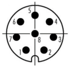
Figure 7 – Power M8 Connector, A-Coded, Male#
M8 Pin |
Description |
|---|---|
1 |
DC Power supply, 12-24V DC (+/- 10%) |
2 |
Opto-isolated IN |
3 |
Opto-isolated OUT |
4 |
GND for opto-isolated I/O |
5 |
Not connected |
6 |
Not connected |
7 |
Not connected |
8 |
GND |
Table 4 – M8 Connector Pin Description
The physical input line Opto-isolated IN (Pin 2) is designated as an opto-isolated input. The operational limits of the opto-isolated input are given in Table 5.
Description |
Limits |
|---|---|
Recommended operating voltage |
+0 to +24 VDC |
Voltage level representing logical 0 |
+0 to +1.4 VDC |
Voltage level representing logical 1 |
> +2.2 VDC |
Absolute maximum voltage |
+30.0 VDC |
The current draw for each input line |
5 to 15 mA |
Table 5 – Electrical Specification for Opto-Isolated Input
The physical output line Opto-isolated OUT (Pin 3) is designated as an opto-isolated output. The operational limits of the opto-isolated output are given in Table 6.
Description |
Limits |
|---|---|
Recommended operating voltage |
+3.3 to +24.0 VDC |
Absolute maximum voltage |
+30.0 VDC |
Maximum output current |
90 mA |
Table 6 – Electrical Specification for Opto-Isolated Output
Caution
Exceeding the operational limits given in Table 4 and Table 5 can cause permanent damage to the device.
3.1 Schemes#
3.1.1 Opto-Isolated OUT/IN Schemes#
The electrical scheme of the Opto-isolated OUT is shown in Figure 8.
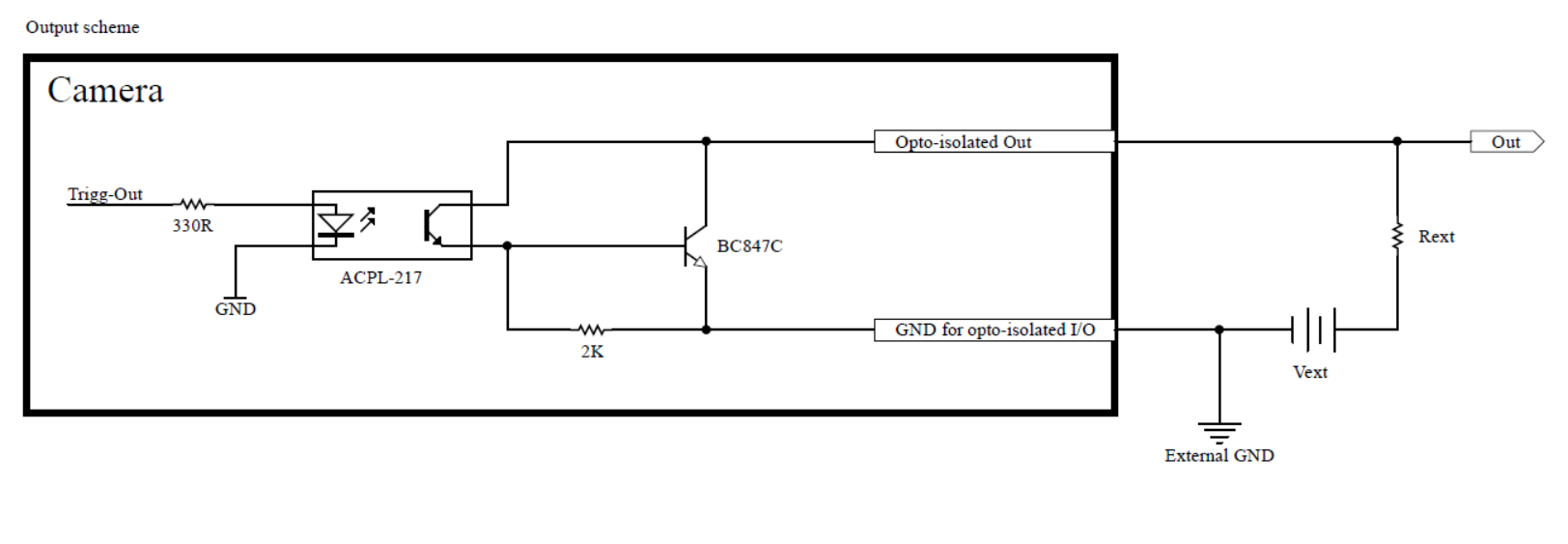
Figure 8 – Opto-Isolated OUT Scheme#
The electrical scheme of the opto-isolated IN is shown in Figure 9.
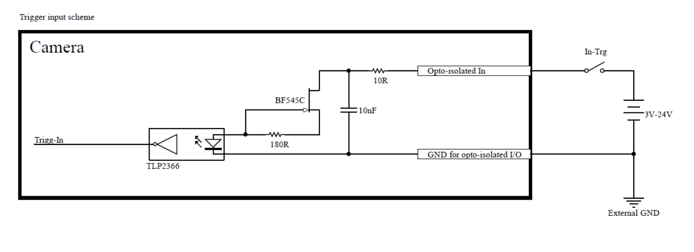
Figure 9 – Opto-Isolated IN Scheme#
3.1.2 Synchronization Scheme#
The electrical scheme of external event multi-camera syncrhonization is shown in Fig. 10.
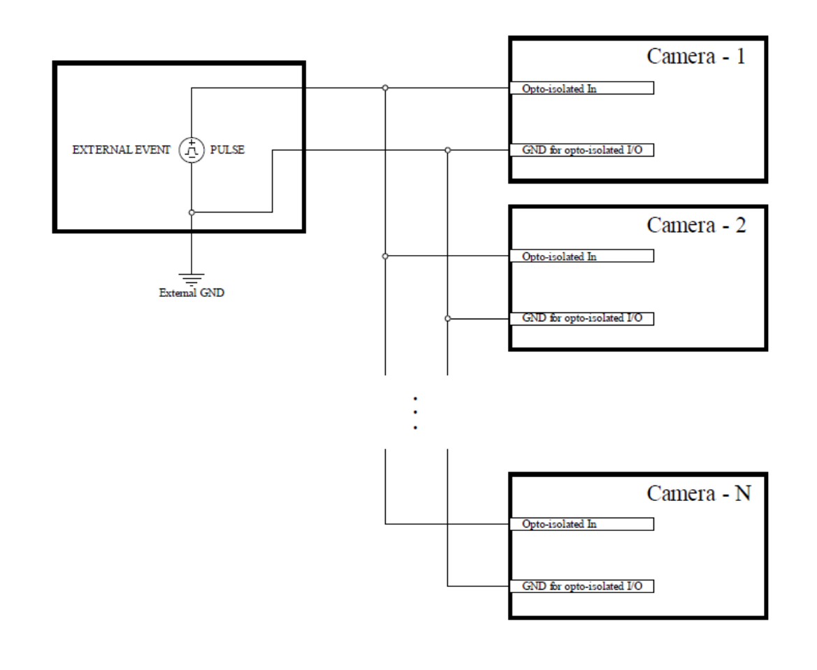
Figure 10 – External Event Synchronization Scheme#
For HW external event synchronization, the External Event Pulse Generator output is connected to the Opto-isolated IN of multiple cameras as shown in Fig. 10. Additionally, the GND for opto-isolated I/O of all cameras is common.
3.2 Recommendations#
3.2.1 External Synchronization Pulse#
When applying an external synchronization pulse, it is recommended to generate the pulse as shown in Fig. 11.
For signal amplitude, follow the electrical specification for the opto-isolated IN given in Table 5.
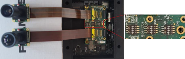
Figure 11 – External Synchronization Pulse#
3.2.2 VSYNC Output#
When operating in external event mode (single or burst mode), the camera outputs the VSYNC signal on the Opto-isolated OUT. The generated VSYNC pulse corresponds to the frame sent to the host. This signal can be used to verify frame jitter (the delay between the applied input trigger pulse and the frame generated).
Software Configuration#
4.1 Camera Settings#
FRAMOS D400e camera series can operate in following modes:
Default Mode
Master Mode
Slave Mode
Genlock Mode (only FRAMOS D400e Global Shutter based cameras)
External Event Mode
External Event Burst Mode
If it is required to synchronize the camera to an external event, the camera must be set to “External Event Mode” or “External Event Burst Mode”.
For additional information on other operating modes, please refer to the FRAMOS Industrial Depth Camera D400e Series - Multi-Camera Synchronization [Ref-2] application note.
4.1.1 Setting Operating Mode#
The external event operating mode can be set for both the Stereo Module and the RGB camera. The “RS2_OPTION_INTER_CAM_SYNC_MODE” option is used for setting the camera operating mode.
// Stereo Module
enum cs_inter_cam_sync_mode
{
    CS_INTERCAM_SYNC_DEFAULT = 0,
    CS_INTERCAM_SYNC_MASTER = 1,
    CS_INTERCAM_SYNC_SLAVE = 2,
    CS_INTERCAM_SYNC_EXTERNAL = 3,
    CS_INTERCAM_SYNC_EXTERNAL_BURST = 4,
    CS_INTERCAM_SYNC_MAX = 5 //enumeration purpose only
};
// RGB Camera
enum cs_inter_cam_sync_mode_color
{
    CS_INTERCAM_SYNC_DEFAULT_COLOR = 0,
    CS_INTERCAM_SYNC_EXTERNAL_COLOR = 1,
    CS_INTERCAM_SYNC_EXTERNAL_BURST_COLOR = 2,
    CS_INTERCAM_SYNC_MAX_COLOR = 3 //enumeration purpose only
};
// Stereo Module Global Shutters
enum cs_inter_cam_sync_mode_gs
{
    CS_INTERCAM_SYNC_DEFAULT_GS = 0,
    CS_INTERCAM_SYNC_MASTER_GS = 1,
    CS_INTERCAM_SYNC_SLAVE_GS = 2,
    CS_INTERCAM_SYNC_FULL_SLAVE_GS = 3,
    CS_INTERCAM_SYNC_EXTERNAL_GS = 259,
    CS_INTERCAM_SYNC_EXTERNAL_BURST_GS = 260,
    CS_INTERCAM_SYNC_MAX = 261 //enumeration purpose only
};
// RGB Camera Global Shutters
enum cs_inter_cam_sync_mode_color_gs
{
    CS_INTERCAM_SYNC_DEFAULT_COLOR_GS = 0,
    CS_INTERCAM_SYNC_EXTERNAL_COLOR_GS = 1,
    CS_INTERCAM_SYNC_EXTERNAL_BURST_COLOR_GS = 2,
    CS_INTERCAM_SYNC_GENLOCK_COLOR_GS = 3,
    CS_INTERCAM_SYNC_MAX_COLOR_GS = 4 //enumeration purpose only
};
4.1.1.1 Setting Operating Mode for the Global Shutter based camera#
An example of configuring the camera’s “External Event Mode” through the Intel RealSense Viewer is shown in Figure 12.

Figure 12 – Setting camera operating mode to external event mode for Global Shutter cameras#
To set the “External Event” operating mode in code, call the “set_option” function with the option’s name and requested value as shown below.
// To set an option to a different value, call set_option with a new value
depth_sensor.set_option(RS2_OPTION_INTER_CAM_SYNC_MODE,
                        CS_INTERCAM_SYNC_EXTERNAL_GS);

color_sensor.set_option(RS2_OPTION_INTER_CAM_SYNC_MODE,
                        CS_INTERCAM_SYNC_EXTERNAL_COLOR);
To set the “Genlock” operating mode in code, call the “set_option” function with the option’s name and requested value as shown below.
// To set an option to a different value, call set_option with a new value

int depth_genlock = 4; //can be set between 4 and 258 with 1-255
                       //frames within burst respectively

depth_sensor.set_option(
    RS2_OPTION_INTER_CAM_SYNC_MODE,
    depth_genlock);

// D455e camera supports color sensor Genlock operating mode

int color_genlock = 3; //set to 3 for genlock mode,
                       //frame burst number is selected from depth

color_sensor.set_option(
    RS2_OPTION_INTER_CAM_SYNC_MODE,
    color_genlock);
An example of configuring “External Event Burst” mode through the Intel RealSense Viewer is shown in Figure 13.
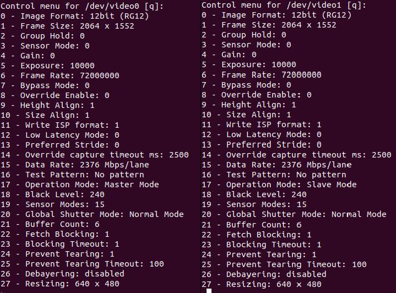
Figure 13 – Setting camera operating mode to external event burst mode for Global Shutter cameras#
To set the “External Event Burst” operating mode in code, call the “set_option” function with the option’s name and requested value as shown below.
// To set an option to a different value, call set_option with a new value

depth_sensor.set_option(
    RS2_OPTION_INTER_CAM_SYNC_MODE,
    CS_INTERCAM_SYNC_EXTERNAL_BURST_GS);

int depth_burst_count = 100;

depth_sensor.set_option(
    RS2_OPTION_EXTERNAL_EVENT_BURST_COUNT,
    depth_burst_count);

color_sensor.set_option(
    RS2_OPTION_INTER_CAM_SYNC_MODE,
    CS_INTERCAM_SYNC_EXTERNAL_BURST_COLOR);

int color_burst_count = 200;

color_sensor.set_option(
    RS2_OPTION_EXTERNAL_EVENT_BURST_COUNT,
    color_burst_count);
4.1.1.2 Setting The Operating Mode for Rolling Shutter based camera#
An example of configuring the camera’s “External Event” operation mode through the Intel RealSense Viewer is shown in Figure 14.
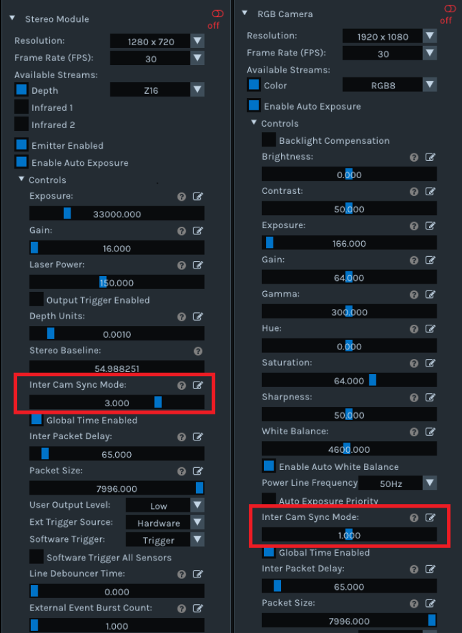
Figure 14 – Setting camera operating mode to external event mode for Rolling Shutter cameras#
To set the “External Event” operating mode in code, call the “set_option” function with the option’s name and requested value as shown below.
// To set an option to a different value, call set_option with a new value

depth_sensor.set_option(RS2_OPTION_INTER_CAM_SYNC_MODE,
                        CS_INTERCAM_SYNC_EXTERNAL);

color_sensor.set_option(RS2_OPTION_INTER_CAM_SYNC_MODE,
                        CS_INTERCAM_SYNC_EXTERNAL_COLOR);
An example of configuring the camera’s “External Event Burst” operation mode through the Intel RealSense Viewer is shown in Figure 15.
Figure 15 – Setting camera operating mode to external event burst mode for Rolling Shutter cameras#
To set the “External Event Burst” operating mode in code, call the “set_option” function with the option’s name and requested value as shown below.
// To set an option to a different value, call set_option with a new value

depth_sensor.set_option(
    RS2_OPTION_INTER_CAM_SYNC_MODE,
    CS_INTERCAM_SYNC_EXTERNAL_BURST);

int depth_burst_count = 100;

depth_sensor.set_option(
    RS2_OPTION_EXTERNAL_EVENT_BURST_COUNT,
    depth_burst_count);

color_sensor.set_option(
    RS2_OPTION_INTER_CAM_SYNC_MODE,
    CS_INTERCAM_SYNC_EXTERNAL_BURST_COLOR);

int color_burst_count = 200;

color_sensor.set_option(
    RS2_OPTION_EXTERNAL_EVENT_BURST_COUNT,
    color_burst_count);
4.1.2 External Event Mode Sources#
When the FRAMOS D400e camera series is set to “Genlock Mode”, “External Event Mode” or “External Event Burst Mode” and the stream is started, the following sources can be selected for generating the pulse applied to the camera:
Hardware
Software
4.1.2.1 Hardware Source#
An example of selecting the hardware trigger source for external event mode through the Intel RealSense Viewer is shown in Figure 16.

Figure 16 – Selecting external event source: Hardware#
To select the hardware trigger source mode in code, call the “set_option” function with the option’s name and requested value as shown below.
// To set an option to a different value, call set_option with a new value

depth_sensor.set_option(RS2_OPTION_EXT_TRIGGER_SOURCE, 1);
color_sensor.set_option(RS2_OPTION_EXT_TRIGGER_SOURCE, 1);
4.1.2.2 Software Source#
An example of selecting the software trigger source for external event mode through the Intel RealSense Viewer is shown in Figure 17.
Figure 17 – Selecting external event source: Software#
To select the software trigger source mode in code, call the “set_option” function with the option’s name and requested value as shown below.
// To set an option to a different value, call set_option with a new value

depth_sensor.set_option(RS2_OPTION_EXT_TRIGGER_SOURCE, 2);
color_sensor.set_option(RS2_OPTION_EXT_TRIGGER_SOURCE, 2);
4.1.2.3 Setting RS2_OPTION_SOFTWARE_TRIGGER_ALL_SENSORS Option#
The “RS2_OPTION_SOFTWARE_TRIGGER_ALL_SENSORS” option is available only when the camera is set to “External Event Software Trigger” mode.
An example of setting “RS2_OPTION_SOFTWARE_TRIGGER_ALL_SENSORS” through the Intel RealSense Viewer is shown in Figure 18.
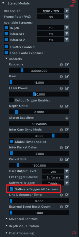
Figure 18 – Setting RS2_OPTION_SOFTWARE_TRIGGER_ALL_SENSORS#
To set the “RS2_OPTION_SOFTWARE_TRIGGER_ALL_SENSORS” in code, call the “set_option” function with the option’s name and requested value as shown below.
// To set an option to a different value, call set_option with a new value

depth_sensor.set_option(
    RS2_OPTION_SOFTWARE_TRIGGER_ALL_SENSORS,
    1
);
4.1.2.4 Executing The Software Trigger#
An example of executing the software trigger through the Intel RealSense Viewer is shown in Figure 19.
Figure 19 – Executing software trigger#
To execute software trigger in code, call the “set_option” function with the option’s name and value as shown below.
// Executing the software trigger

depth_sensor.set_option(RS2_OPTION_SOFTWARE_TRIGGER, 1);
color_sensor.set_option(RS2_OPTION_SOFTWARE_TRIGGER, 1);
Note
All the given examples of configuring the camera to the external event software trigger, genlock and external event burst software trigger operating mode can be found in the “rs-software-trigger” example that is part of the D400e v2.1.0 or newer software packages.
Hardware Validation#
External Event Camera Synchronization validation is performed using a FRAMOS D435e camera and a Function Generator.
5.1 Frame Jitter#
As mentioned in Chapter 2.1, frame jitter is less than 1/FPS when external event synchronization is used.
The following test scenario is used for validation:
Resolution: 1280x720
Streams: Depth, Infrared, Color
Frame Rate: 30 FPS
External Event Frequency: 14 Hz
Results for more than 10000 trigger pulses, that were applied to the camera synchronization interface, are given in Table 6 and shown in Figure 20.
Measurement |
Mean [ms] |
Min [µs] |
Max [ms] |
Std Dev [ms] |
|---|---|---|---|---|
Frame Jitter |
16.70 |
2.628 |
33.32 |
9.624 |
Table 7 – Frame Jitter Result on 10000 Trigger Pulses
Figure 20 – Real Time Frame Jitter Histogram#
SYNC PULSE in Figure 20 is the trigger pulse applied to the camera and VSYNC represents the start of the generated frame that is sent to the host.
The histogram shows different frame jitter captured, varying from 2.63 µs to 33.32 ms.
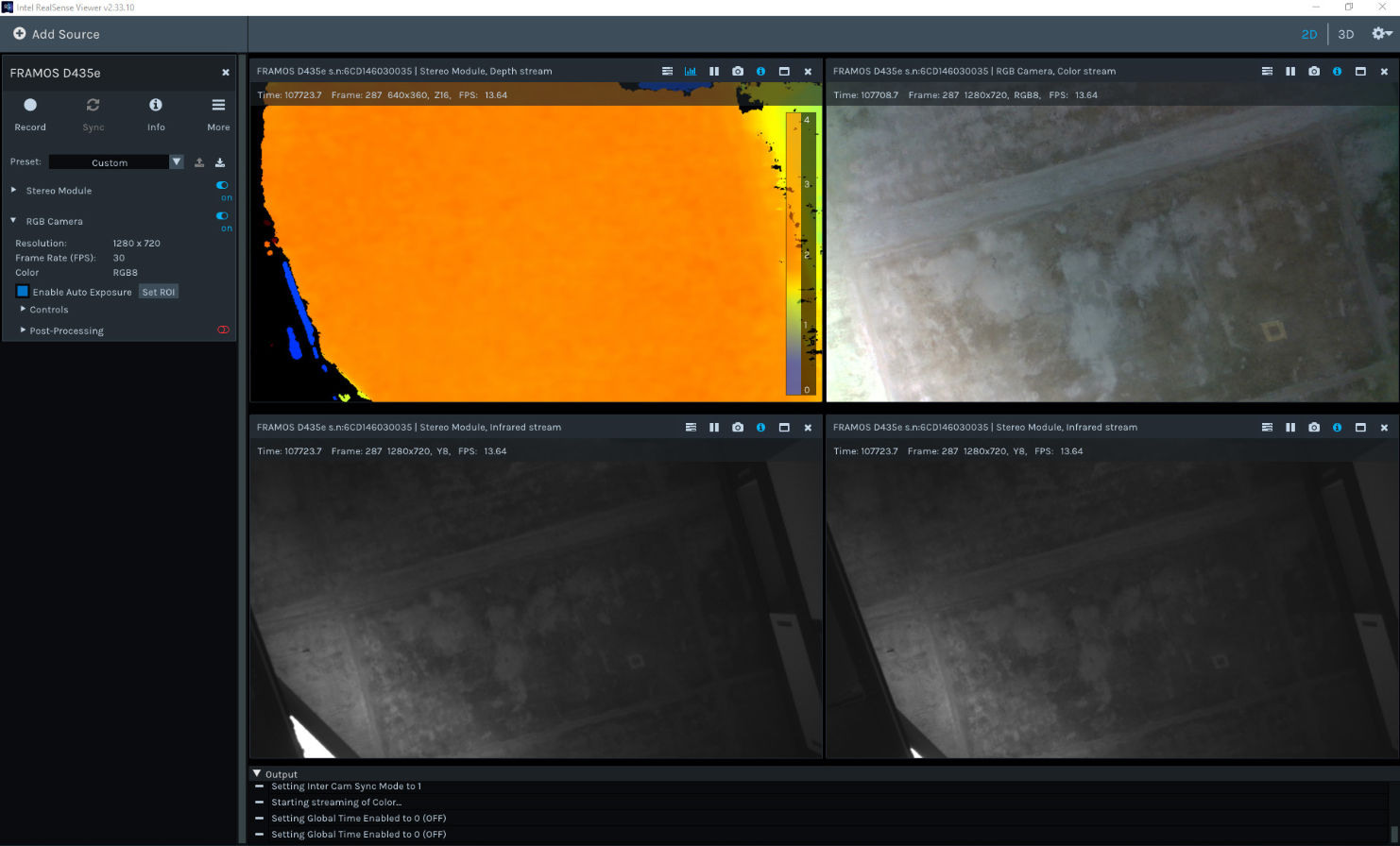
Figure 21 – FRAMOS D435e Camera Streaming in External Event Mode#
The FRAMOS D435e camera streaming in “External Event” mode is shown in Figure 21. It is visible from the figure that the acquired framerate corresponds to external event pulse frequency.
Troubleshooting#
This chapter provides troubleshooting information for various issues related to synchronizing D400e cameras with external events.
6.1 Software Trigger Issues#
6.1.1 Exceptions#
Certain options related to software triggering are dependent on other options. For this reason, the RealSense library may throw exceptions if using those features when the camera is not in its expected operating mode.
Recommended steps to enable software triggering mode and send software triggers to camera are to:
Set the operating mode to “External Event” operating mode (Refer to Chapter 4.1.1).
Set the external trigger source to “Software” (Refer to Chapter 4.1.2).
Execute “Software Trigger” (Refer to Chapter 4.1.2).
The following exception can be thrown when changing the external trigger source, and camera operating mode is not set to “External Event” operating mode.

Figure 22 – Changing “Ext Trigger Source” in wrong “Inter Cam Sync Mode”#
An exception can be thrown when trying to execute “Software Trigger” and an external trigger source is not set to “Software” as shown in Figure 23.

Figure 23 – Executing “Software Trigger” with wrong “Ext Trigger Source”#
6.1.2 Rendering#
When using the software trigger, all frames may not be visualized in RealSense Viewer as it can be seen in Figure 24: one of the infrared sources shows a different frame number. Frames are not dropped by the library but are just not shown in the RealSense Viewer.
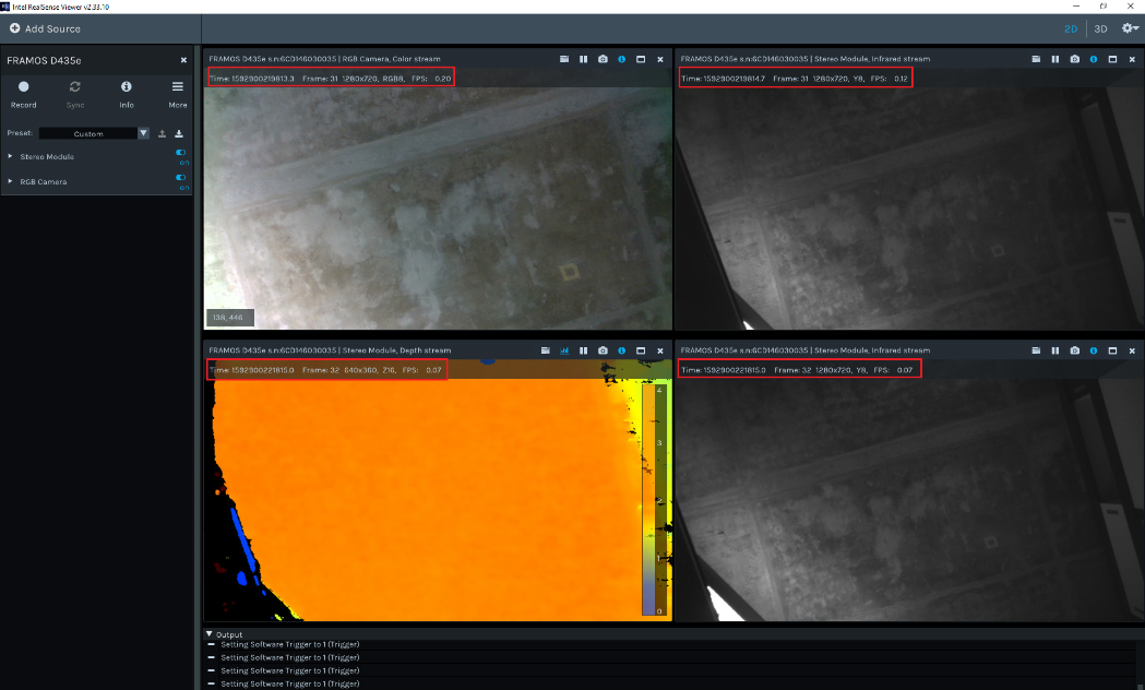
Figure 24 – Frame numbers vary when synchronization in RealSense Viewer is enabled#
When using external trigger mode, disable synchronization between the pointcloud and the texture using the padlock in the upper right corner in RealSense Viewer as shown in Figure 25.
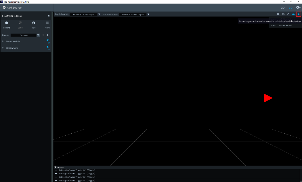
Figure 25 – Disable synchronization between the pointcloud and the texture#
6.1.3 Post-processing#
Some of the post-processing algorithms require multiple frames for calculations. If post-processing is active, depth information might not be updated correctly, as shown in Figure 26.
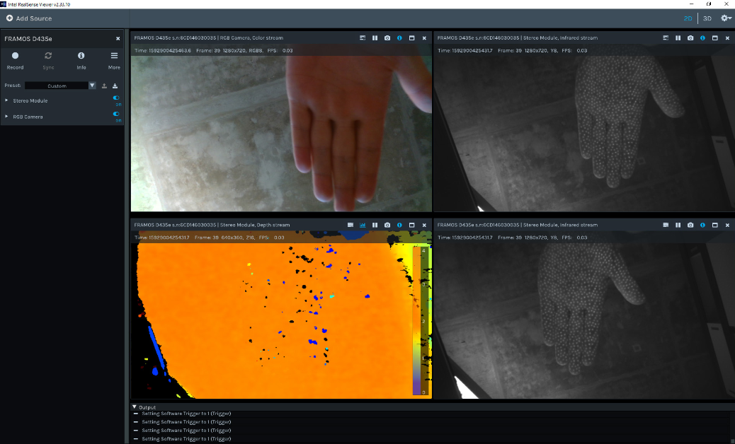
Figure 26 – Post-processing active#
With post-processing disabled, depth information is properly updated as shown in Figure 27.

Figure 27 – Post-processing disabled#
6.2 Genlock Known Issues#
There is a known issue with the Intel D400 global shutter based cameras when using the genlock functionality (Issue 7628): when streaming is enabled, the camera generates a burst of frames without an external trigger being applied on the synchronization interface.
For D400e cameras, the extra frames described above are filtered out inside the camera when streaming is enabled, effectively masking out the issue as seen from the host’s perspective. This can lead to a different issue on D400e cameras in an case external trigger is applied immediately after the stream is started. As the camera internally still generates a burst of frames, because of the abovementioned issue, a newly applied trigger does not start new burst of frames (it is ignored) but will disable frame filtering, consequently sending the remaining frames from initial burst.
The example below illustrates the problem:
Set Inter Cam Sync Mode value to 250, this will enable “Genlock” operating mode and the camera should produce and send a burst of 247 frames (refer to Chapter 4.1.1).
Set the external trigger source to “Software” (refer to Chapter 4.1.2).
Enable stream for the Stereo Module.
Execute “Software Trigger” (Refer to Chapter 4.1.2) immediately after enabling the stream.
The number of frames acquired on the host is less than the expected 247 frames, as shown on Figure 28. In the presented case only 206 frames were acquired by the host.
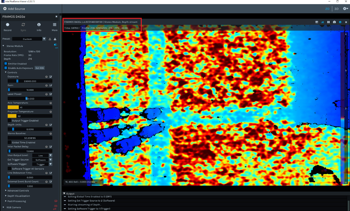
Figure 28 – Genlock issue for D400e series camera#
Note
To avoid the described issue on D400e cameras, it is recommended to wait some time after the stream is enabled before applying the external trigger. The wait time is calculated by dividing the number of frames in the burst by the frame rate.
There is another issue with the Genlock functionality of a D455e color sensor where the frames have a slight purple hue. This issue is also observed on an Intel D455 model camera.
References#
FRAMOS Industrial Depth Camera D400e Series - Tuning System For Best Performance, FRAMOS GmbH.
FRAMOS Industrial Depth Camera D400e Series - Multi-Camera Synchronization, FRAMOS GmbH.
FRAMOS Industrial Depth Camera D400e Series - User Manual, FRAMOS GmbH.
External Synchronization of Intel RealSense Depth cameras, v1.0, Intel.
Revision History#
Date |
Version |
Changes |
|---|---|---|
2020-06-30 |
1.0.0 |
Initial release |
2021-01-15 |
1.1.0 |
Added chapter “Genlock Operation”; Added chapter “External Event Burst Mode”; Updated chapter “Functional Description”; Updated chapter “Software Configuration” |
2021-07-15 |
1.2.0 |
Updated chapter “Hardware Configuration”; Updated “References”; Updated chapter “Genlock Operation” |
2021-10-15 |
1.2.1 |
Removed description from figures |
2023-07-28 |
1.3.0 |
Updated chapter “Overview”; Updated chapter “Genlock Operation”; Updated chapter “Genlock Known Issues” |
Note
This document replaces and supersedes the application note “FRAMOS Industrial Depth Camera D435e - External Event Camera Synchronization” v1.1.0.