
Tuning System For Best Performance#
Overview#
The FRAMOS Industrial Depth Camera D400e Series - Tuning System For Best Performance application note provides tips and recommendations on setting system and camera settings to achieve best performance from FRAMOS D400e camera series.
System Settings#
General Recommendations#
There are number of system related parameters and conditions that could negatively affect the system performance and consequently limit the maximum achievable performance of the FRAMOS Industrial Depth camera D400e series used in such a system. Perhaps the most important factor to consider is selection and configuration of the Network Interface Card (NIC).
It is recommended to use a Gigabit Ethernet NIC with a PCI-E interface supporting the Jumbo Frames feature.
Note
For best performance, FRAMOS recommends Intell® PCI-E network interface cards.
Network Related Settings#
The following network related settings should be adjusted to achieve optimal performance:
Jumbo Frames
Receive Buffers
Using Jumbo Frames reduces packet overhead and workload on the target PC. This is achieved by transmitting a small number of large packets instead of a large number of smaller packets.
The Receive Buffers feature of the NIC represents reserved memory used to buffer incoming data. It is recommended to increase the buffer size of the incoming packets (Receive Buffers) to the maximum supported value in order to decrease packet loss probability under high system load.
Feature availability and limits can differ between NIC vendors and operating systems. The descriptions of driver settings in the following chapters are based on Intel® NICs. THe settings are shown for Microsoft Windows and Linux operating systems.
Network Interface Optimization for the Windows Operating System#
Driver settings are configured through the driver properties dialog.
Open Control Panel -> Network Connections (
ncpa.cplthrough the “Run” app or directly from the CMD).Right-click the target network interface card and choose Properties.
Press the Configure button below the physical network interface name.
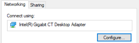
Figure 1 – Access to NIC driver settings#
Open the Advanced tab.
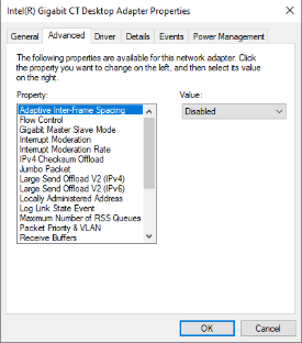
Figure 2 – NIC - advanced driver settings#
Jumbo Frames / Packets - Network Interface Cards#
The Jumbo Frames (or Jumbo Packet) feature is disabled by default on most NICs, so it needs to be manually enabled within the device driver property window as shown on Figure 3. To enable Jumbo Frames, set the property to its maximum value.
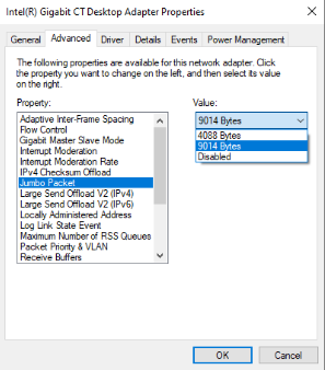
Figure 3 – NIC - Enabling Jumbo Packet on Windows#
Note
In network configurations where the camera is not connected directly to the NIC but via other network components (i.e., gigabit switches), it is required to enable Jumbo Frames on all the components used in the network’s path.
Receive Buffers - Network Interface Cards#
The Receive Buffers property can be accessed via the driver property window as shown on Figure 4. Increase the value to the maximum supported setting.
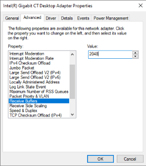
Figure 4 – NIC - Accessing Receive Buffers on Windows#
Network Interface Optimization for Linux Operating System#
Jumbo Frames#
To enable Jumbo Frames temporarily, run:
sudo ip link set <ethx> mtu <size>
or:
sudo ifconfig <ethx> mtu <size>
Where:
<ethx>represents the name of the network interface that connects the PC to the FRAMOS D400e camera series.<size>is the desired frame/packet size in bytes (for example9000).
This configuration remains active until reboot.
Note
The ip utility may not be available on all Linux distributions.
Note
Refer to the Linux distribution documentation for information on permanent Jumbo Frame configuration.
Receive Buffers#
To increase the Receive Buffers size on the Linux operating system you can use the “ethtool” provided by many Linux distributions.
Use:
sudo ethtool -G <ethx> rx <size>
Where:
<ethx>is the name of the network interface in question.<size>is the desired number of Receive Buffers.
If “ethtool” isn’t provided by your Linux distribution, please refer to the distribution documentation for alternatives.
Application Environment Considerations#
For best performance it is recommended to run applications using the FRAMOS Industrial Depth Camera D400e series on a dedicated system with a freshly installed operating system.
Large numbers of concurrent application processes and background services may negatively affect software application performance.
Antivirus software, firewalls, third-party filter drivers and network traffic monitoring software may also affect performance as they monitor the incoming packets at different network stack layers.
Therefore, it is recommended to work from a fresh system installation in order to minimize the chances of unwanted performance degradation and to only keep essential services on that won’t have a noticeable impact on performance.
Camera Settings#
Inter Packet Delay#
Inter Packet Delay (GenICam feature GevSCPD) is the delay introduced by
the camera between sending two consecutive packets on the stream channel.
This delay reduces effective network load (on NIC or switch) and creates timeslots for processing packets from other devices on the network.
Inter Packet Delay is especially useful when multiple cameras are streaming to one PC through a single Network Interface Card.
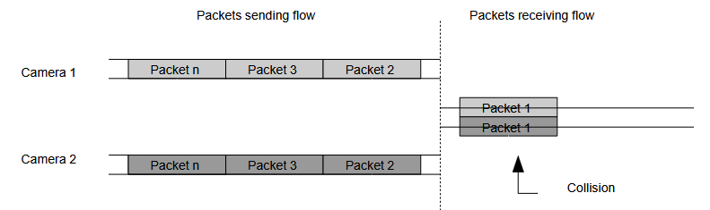
Figure 5 – Packet flow when inter packet delay is not used#
If the Inter Packet Delay feature is not used, excessive packet collissions may occur which can result in data loss, as illustrated in Fig. 5.
Packets from two cameras are sent to the PC over the same network connection. Without any Inter Packet Delay set, collission between packets from different cameras may occur in case both cameras stream packets at the same time. Fig. 6 illustrates a well configured Inter Packet Delay that prevents collissions.

Figure 6 – Packet flow with properly configured inter packet delay#
Assuming a Packet Size (the GevSCPSPacketSize GenICam feature) of 1500 bytes, the effective
Ethernet packet size, including the inter-frame gap, preamble, header and CRC on the wire, is 1538 bytes.
On a Gigabit Ethernet network, transmitting one byte takes approximately 8ns. The full packet transfer thus takes around 12,3 microseconds, making the camera’s speed 81274 packets per second.
In case two cameras are streaming to one NIC, the Inter Packet Delay should be a bit larger than the time required to transfer one packet, in order to ensure that packets from the second camera will fit in the vacant time slot.
Increasing Inter Packet Delay extends frame transfer time which means higher latency but can also result in lower framerates. FOr example, if one camera is producing 30000 packets per second (50 fps, 600 packets per frame), the total packet transfer time (packet + inter packet delay) must not exceed 33,3 microseconds in order to preserve framerate.
In a more complex system, including multiple cameras with multiple streams, determining Inter Packet Delay is not so intuitive anymore. It is advise to iteratively increase Inter Packet Delay until a stable stream is achieved. On the other hand, Inter Packet Delay must not be set too high due to the latency increase and possible lower framerates.
Using an empirical approach, Inter Packet Delay should be determined quickly.
Example for Adjusting Inter Packet Delay#
One camera is configured with the following stream profile:
1280 x 720
30 FPS (Stereo Module and RGB Camera)
Wireshark is used for network analysis. Results may vary with different NICs and its configurations.
Note
Wireshark is a widely used network protocol analyzer and is used for network analysis and troubleshooting. It is advised for analysis when adjusting Inter Packet Delay.
Case 1:#
Stereo Module Inter Packet Delay: 0
Stereo Module Packet Size: 7996
RGB Camera Inter Packet Delay: 0
RGB Camera Packet Size: 7996
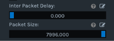
As a consequence of inadequate Inter Packet Delay, there are no streams, as shown in Fig. 7.
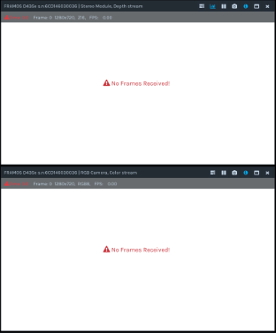
Figure 7 – Inter Packet Delay set to 0 - no frames received#
Additionally, there is an excessive number of Packet Resend requests issued from PC to camera as shown in Fig. 8. Packet Resend is the mechanism used to recover the missing packets in case of packet loss.

Figure 8 – Wireshark log for Packet Resend requests, Case 1#
Case 2:#
Stereo Module Inter Packet Delay: 25
Stereo Module Packet Size: 7996
RGB Camera Inter Packet Delay: 25
RGB Camera Packet Size: 7996
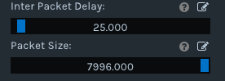
With increased INter Packet Delay value for both Stereo and RGB modules, streams are active, but due to insufficient Inter Packet Delay, there is a noticeable framerate drop.
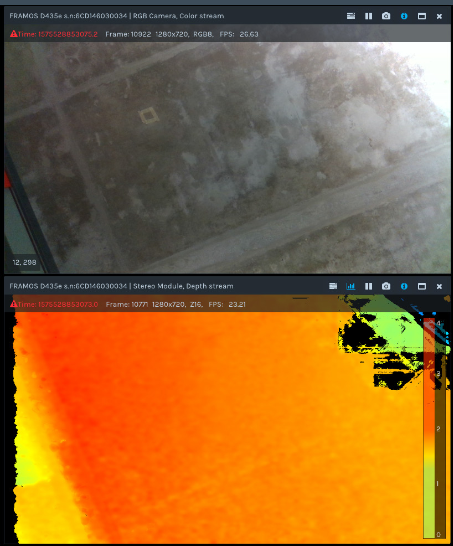
Figure 9 – Inter Packet Delay too small - frames received, frame rate drops#
For Case 2, there is a smaller number of Packet Resend requests compared to Case 1, as shown on Fig. 10.
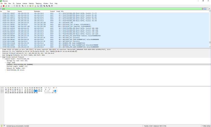
Figure 10 – Wireshark log for Packet Resend requests, Case 2#
Case 3:#
Stereo Module Inter Packet Delay: 65
Stereo Module Packet Size: 7996
RGB Camera Inter Packet Delay: 65
RGB Camera Packet Size: 7996
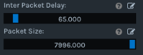
With Inter Packet Delay values for both Stereo and RGB modules increased further, streams retain a stable 30FPS.

Figure 11 – Inter Packet Delay optimal - frames received, frame rate stable#
Analyzing the network traffic with Wireshark for Case 3 shows that the number of Packet Resend requests dropped to a minimum as seen on Fig. 12.
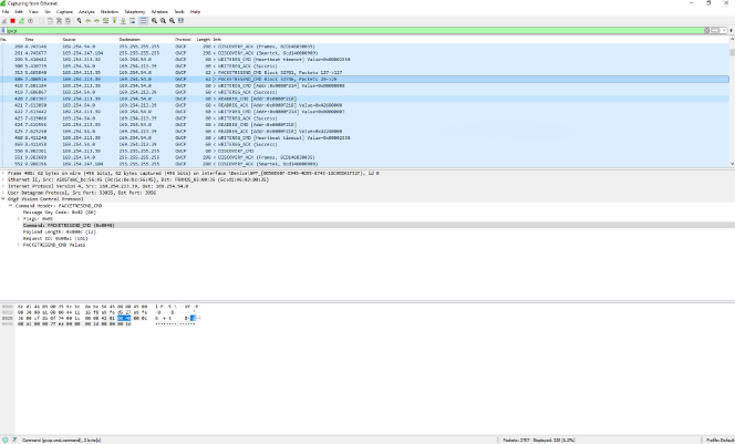
Figure 12 – Wireshark log for Packet Resend requests, Case 3#
Note
Regardless of the set Inter Packet Delay value, Packet Resend requests may still occur occasionally due to packet loss caused by high system or network load.
Example for Three Cameras Streaming to One NIC#
Three cameras are streaming packets of 1500 bytes to one NIC simultaenously. Inter Packet Delay should be set so that packets from all three cameras are serialized to the PC’s NIC. Setting inter packet delay to 25μs (12,3μs + 12,3μs ~= 25μs) on each camera will ensure that packets from the other two cameras will fit in the gap between two consecutive packets.
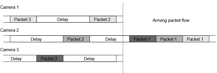
Figure 13 – Packet flow example with three cameras and properly configured inter packet delay#
Setting Inter Packet Delay#
The RS2_OPTION_INTER_PACKET_DELAY option is used for camera Inter Packet Delay configuration,
examples of which, through the Intel RealSense Viewer can be seen on Fig. 14.
In relation to Jumbo Frames/PAckets, the FRAMOS D400e camera series’ Packet Size can be adjusted using RealSense Viewer as well.
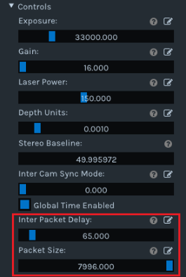
Figure 14 – Inter Packet Delay feature in RealSense Viewer#
To set Inter Packet Delay in code, call the set_option function with the option’s name and the requested value, as shown below.
// To set an option to a different value, call set_option with a new value
sensor.set_option(
    RS2_OPTION_INTER_PACKET_DELAY,
    inter_packet_delay);
Configuring Packet Size can be done in the same way using:
// To set an option to a different value, call set_option with a new value
sensor.set_option(
    RS2_OPTION_PACKET_SIZE,
    packet_size);
Tuning Inter Packet Delay with Packet Statistic Feature#
Tuning the Inter Packet Delay is an adjustment process aimed to reduce the amount of Packet Resend requests while preserving the configured framerate
Packet resend activity can be measured through Wireshark or through the Packet Statistic feature.
When RealSense logging DEBUG severity) is enabled, packet statistics are logged every 10 seconds in the RealSense log file or terminal.
Enable logging in C++:
int main(int argc, char * argv[]) try
{
   rs2::log_to_file(
       RS2_LOG_SEVERITY_DEBUG,
      "/path/to/file.txt");
}
Enable logging in Python:
rs.log_to_file(
    rs.log_severity.debug,
    file_path='./path/to/file.txt')
An example of a logged packet statistic is given below:
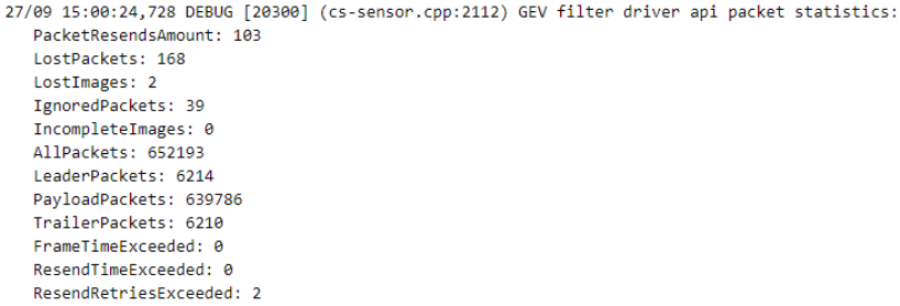
Tune the Inter Packet Delay while monitoring the
PacketResendsAmount. This can be done during the stream.
Note
The Packet Statistic feature is available in the D400e v2.2.0 (or higher) software package.
GigE Vision Drivers#
The D400e software package comes with two different GigE Vision (GEV) drivers:
FRAMOS GigE Vision Filter Driver – a high-performance network filter driver
GigE Vision Socket Driver – a driver that uses the system socket’s API
The GigE Vision socket driver is included in the CameraSuite library while the FRAMOS GigE Vision filter driver is a standalone installation package.
During Camera Suite library installation, the user will be prompted to install the FRAMOS GigE Vision filter driver as shown in Fig. 15 and Fig. 16.
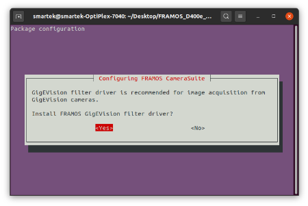
Figure 15 – CameraSuite – Filter driver installation [Linux]#

Figure 16 – CameraSuite – Filter driver installation [Windows]#
Note
Only one driver can be used on a system. Framos recommends the usage of a filter driver which is designed to ensure optimal performance.
Note
System tuning recommendations should be applied regardless of driver version.
Note
Socket drivers are available from the D400e v2.4.0 (or higher) software package.
Checking the Driver Used#
The filter driver has precedence over the socket driver.
The CameraSuite library will check if the filter driver is present on the system and will try to load it. If it is not installed or it fails to load, the socket driver will be used instead.
Driver selection information is available through the RealSense logging mechanism and can be observed at the start of an image stream. An example of it is depictd in Fig. 17.
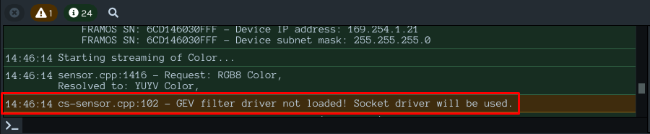
Figure 17 – RealSense Viewer using socket driver#
Revision History#
Date |
Version |
Changes |
|---|---|---|
2020-06-30 |
1.0.0 |
Initial release |
2021-07-15 |
1.1.0 |
Added chapter “Tuning Inter Packet Delay with Packet Statistic Feature” |
2021-10-15 |
1.2.0 |
Updated packet statistic chapter and added GigE Vision Drivers chapter |
Note
This document replaces and supersedes the application note “FRAMOS Industrial Depth Camera D435e - Tuning System for Best Performance” version 1.0.0.