
Multi-Camera Synchronization#
Overview#
The FRAMOS Industrial Depth Camera D400e Series - Multi-Camera Synchronization application note provides tips and recommendations on how to configure multiple FRAMOS D400e cameras to achieve synchronous streaming.
Multiple D400e cameras, in default configuration, will capture data at different points in time and streams from multiple cameras will therefore not be synchronized. Synchronous streaming from multiple cameras can be achieved by utilizing the camera’s external synchronization interface. Additionally, the cameras need to be configured via software interface in a way that the system consists of one master device and multiple slave devices.
To arrange a multi camera system, additional restrictions as, e.g. bandwidth limitations and NIC settings, need to be considered. Refer to FRAMOS Industrial Depth Camera D400e Series - Tuning System For Best Performance appnote [Ref-1] for tips on how to achieve the best performance with a multi-camera system.
Note
With the D400e series multi-camera system, only the streams from the same camera model can be synchronized (D435e with D435e, D415e with D415e, D455e with D455e).
Hardware Configuration#
The FRAMOS Industrial Depth Camera D400e series is equipped with an industrial grade M8 connector used for power supply and external synchronization through the I/O interface as shown in Figure 1 and described in Table 1.

Figure 1 – Power M8 Connector, A-Coded, Male#
M8 Pin |
Description |
|---|---|
1 |
DC Power supply, 12-24V DC (+/- 10%) |
2 |
Opto-isolated IN |
3 |
Opto-isolated OUT |
4 |
GND for opto-isolated I/O |
5 |
Not connected |
6 |
Not connected |
7 |
Not connected |
8 |
GND |
Table 1 – M8 Connector Pin Description
The physical input line Opto-isolated IN (Pin 2) is designated as an opto-isolated input. The operational limits of the opto-isolated input are given in Table 2.
Description |
Limits |
|---|---|
Recommended operating voltage |
+0 to +24 VDC |
Voltage level representing logical 0 |
+0 to +1.4 VDC |
Voltage level representing logical 1 |
> +2.2 VDC |
Absolute maximum voltage |
+30.0 VDC |
The current draw for each input line |
5 to 15 mA |
Table 2 – Electrical Specification for Opto-Isolated Input
The physical output line Opto-isolated OUT (Pin 3) is designated as an opto-isolated output. The operational limits of the opto-isolated output are given in Table 3.
Description |
Limits |
|---|---|
Recommended operating voltage |
+3.3 to +24.0 VDC |
Absolute maximum voltage |
+30.0 VDC |
Maximum output current |
90 mA |
Table 3 – Electrical Specification for Opto-Isolated Output
Warning
Exceeding the operational limits given in Table 2 and Table 3 can cause permanent damage to the device.
2.1 Schemes#
2.1.1 Opto-Isolated OUT/IN Schemes#
Electrical scheme of Opto-isolated OUT is shown in Figure 2.
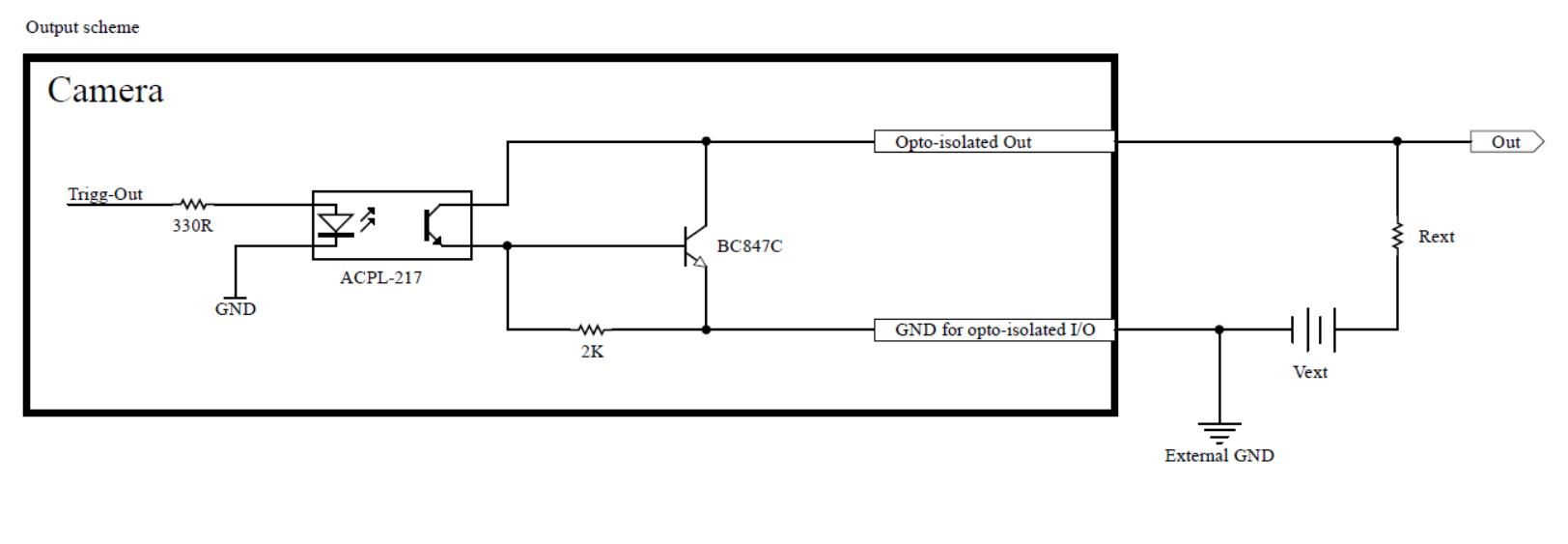
Figure 2 – Opto-Isolated OUT Scheme#
The electrical scheme of the Opto-isolated IN is shown in Figure 3.

Figure 3 – Opto-Isolated IN Scheme#
2.1.2 Synchronization Scheme#
The electrical synchronization scheme between the “Master Camera” and multiple “Slave Cameras” is shown in Figure 4. The “Master Camera” black box presents a simplified Opto-isolated OUT scheme, while the “Slave Camera” black boxes present simplified Opto-isolated IN schemes.
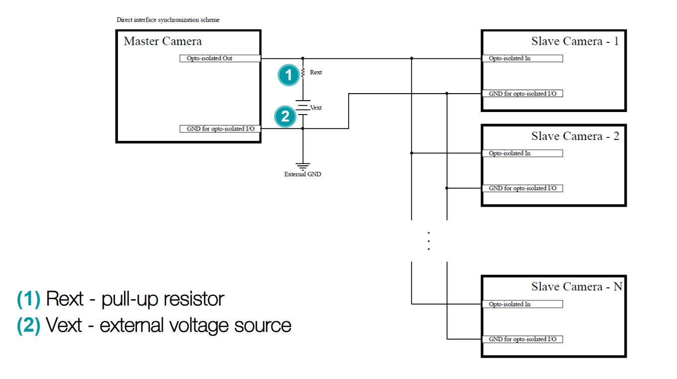
Figure 4 – Synchronization Scheme#
For HW synchronization of the Opto-isolated OUT of the “Master Camera”, it must be connected to the Optoisolated IN of multiple “Slave Cameras” as shown on Figure 4. Additionally, the GND for opto-isolated I/O of all cameras is common.
2.2 Restrictions#
Using the synchronization scheme presented in Figure 4, one “Master Camera” can trigger at least 7 “Slave Cameras”, meaning that at least 8 cameras can be synchronized this way. The value of the Rext resistor should be selected carefully, considering the number of cameras and the external voltage source Vext used in the system.
Number of Devices in Multi-Camera System |
Vext |
Rext |
|---|---|---|
2 (1 Master + 1 Slave) |
24V |
2K2 |
4 (1 Master + 3 Slaves) |
24V |
1K |
8 (1 Master + 7 Slaves) |
24V |
390R |
Table 4 – Recommended value for Rext resistor in different systems
Two important criteria must be satisfied when selecting the value of Rext resistor: the minimum value of the resistor is limited by the absolute maximum current of the opto-isolated output on the “Master Camera”; the maximum value of the resistor is limited by the voltage level representing a logical “1” of the opto-isolated input on the “Slave Camera”. The recommended value of the Rext resistor for different systems is presented in Table 4.
Another important aspect is the resistor power rating. It is recommended to use the highest possible value of Rext resistor in a system, range limited by the above two criteria, to prevent excess power consumption and heating of the Rext resistor. For example, for a system with 8 cameras, as shown in Table 4, using Rext 390R and Vref 24V, the maximum dissipation on the Rext resistor is P = 1.47W.
Note
Connecting more than 7 “Slave Cameras” in a multi-camera system, as shown in Figure 4, could decrease the voltage level representing a logical 1 at the Opto-isolated IN below the value given in the electrical specification for the opto-isolated input (see Table 2), and might lead to incorrect level recognition. It is recommended to verify that the voltage level at the opto-isolated input is inside the specified range with an oscilloscope.
Warning
The value of the Rext resistor should be selected carefully so that the absolute maximum current of the opto-isolated output on the “Master Camera” is not exceeded. Using a resistor with a lower value than recommended can cause permanent damage to the camera.
Software Configuration#
3.1 Software Prerequisites#
For validation purposes, the “LED Matrix Display” and “Intel RealSense Viewer” applications are used.
The LED Matrix Display is an application which presents the movement of the LEDs as shown in Figure 5.
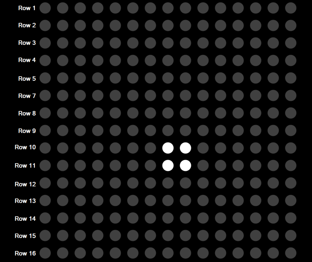
Figure 5 – LED Matrix Display Application#
The LEDs are moving at the desired frequency. By setting the appropriate LED moving frequency (considering the camera frame rate), it is possible to visualize if the cameras are synchronized or not.
The Intel RealSense Viewer is used for capturing the infrared stream from the left imager and setting the required configuration on multiple FRAMOS D400e cameras.

Figure 6 – FRAMOS D435e Camera streaming in Intel RealSense Viewer#
3.2 Camera Settings#
FRAMOS D400e camera series can operate in following modes:
Default Mode
Master Mode
Slave Mode
Genlock Mode
External Event Mode
By default, the camera is in “Default Mode”. Considering a multi-camera system, “Default Mode” means asynchronous streaming among cameras. When operating in “Master Mode”, the camera outputs a synchronization signal on the Opto-isolated OUT as long as the “Output Trigger Enabled” option is enabled. In “Slave Mode”, if there is no signal on the Opto-isolated IN, the camera streams asynchronously in regard to other cameras in the system. If there is a proper signal on the Opto-isolated IN, the slave camera is synchronized with the master camera.
When using the FRAMOS D400e camera series in a standalone application/system, the “Default Mode” is the recommended operation mode.
If it is required to hardware synchronize cameras in a multi-camera system, only one camera is set to “Master Mode” and the others to “Slave Mode”. The camera that is set to “Master Mode” must have the “Output Trigger Enabled” option enabled.
3.2.1 Setting Operating Mode#
The “RS2_OPTION_INTER_CAM_SYNC_MODE” option is used for setting the camera’s operating mode. The “RS2_OPTION_OUTPUT_TRIGGER_ENABLED” option is used for setting the “Output Trigger Enabled” option.
// Stereo Module
enum cs_inter_cam_sync_mode
{
    CS_INTERCAM_SYNC_DEFAULT = 0,
    CS_INTERCAM_SYNC_MASTER = 1,
    CS_INTERCAM_SYNC_SLAVE = 2,
    CS_INTERCAM_SYNC_EXTERNAL = 3,
    CS_INTERCAM_SYNC_EXTERNAL_BURST = 4,
    CS_INTERCAM_SYNC_MAX = 5 //enumeration purpose only
};

// RGB Camera
enum cs_inter_cam_sync_mode_color
{
    CS_INTERCAM_SYNC_DEFAULT_COLOR = 0,
    CS_INTERCAM_SYNC_EXTERNAL_COLOR = 1,
    CS_INTERCAM_SYNC_EXTERNAL_BURST_COLOR = 2,
    CS_INTERCAM_SYNC_MAX_COLOR = 3 //enumeration purpose only
};

// Stereo Module Global Shutters (D435e)
enum cs_inter_cam_sync_mode_gs
{
    CS_INTERCAM_SYNC_DEFAULT_GS = 0,
    CS_INTERCAM_SYNC_MASTER_GS = 1,
    CS_INTERCAM_SYNC_SLAVE_GS = 2,
    CS_INTERCAM_SYNC_FULL_SLAVE_GS = 3,
    CS_INTERCAM_SYNC_EXTERNAL_GS = 259,
    CS_INTERCAM_SYNC_EXTERNAL_BURST_GS = 260,
    CS_INTERCAM_SYNC_MAX = 261 //enumeration purpose only
};
An example of configuring the camera’s operation mode through the Intel RealSense Viewer is shown in Figure 7.
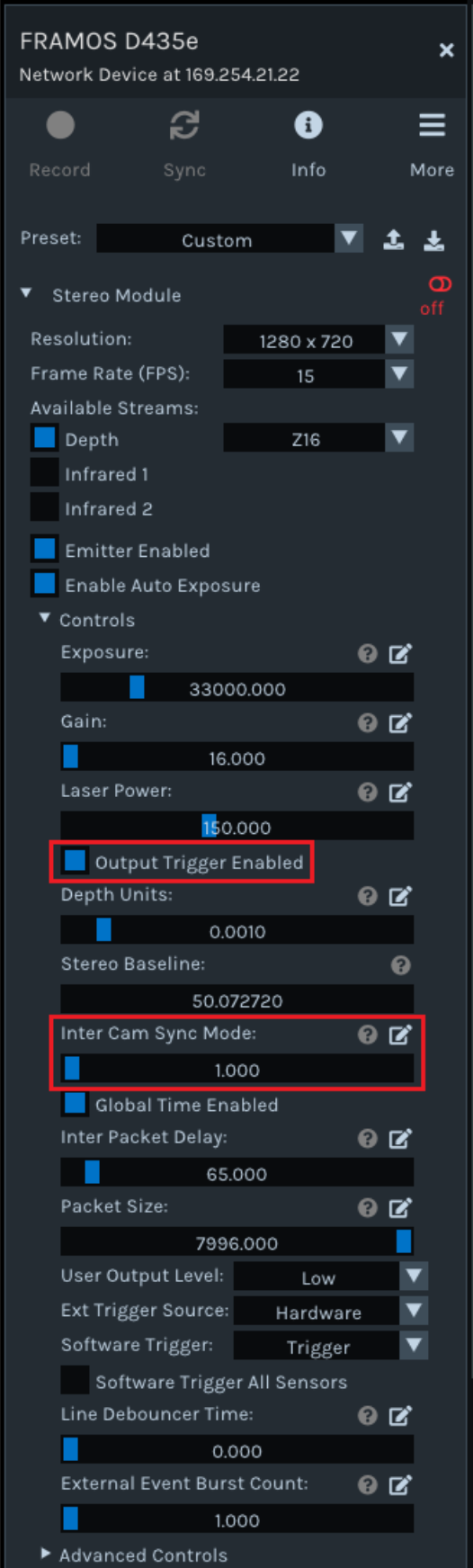
Figure 7 – Setting the camera’s operation mode to master mode#
To set the operating mode in code, call the “set_option” function with the option’s name and requested value as shown below.
// To set an option to a different value, call set_option with a new value

sensor.set_option(RS2_OPTION_INTER_CAM_SYNC_MODE, requested_value);
3.2.2 Additional remarks#
In a multi-camera system, where multiple cameras are streaming to one network card on a PC, FRAMOS D400e cameras and network settings must be tuned to achieve best performance. Following recommendations given in the “FRAMOS Industrial Depth Camera D400e - Tuning System For Best Performance” application guide, Inter Packet Delay and Packet Size options need to be adjusted, taking the configured Resolution and Frame Rate options into consideration.
For example, in a system with two FRAMOS D400e cameras connected to one network card and a streaming configuration as follows:
Resolution: 1280x720
Frame Rate: 15
Packet Size: 1500,
the recommended value for Inter Packet Delay is:
Inter Packet Delay: 50
Hardware Validation#
Multi-camera synchronization validation is performed using two FRAMOS D435e cameras pointing at the LED Matrix Display Application running on a Desktop PC. Capturing the fast-moving LEDs with both cameras simultaneously provides visual verification if the cameras are capturing images at the same time and frame rate.
With the remarks given in Chapter 3.2, one camera is configured to master operating mode, and the other to slave operating mode, as shown in Figure 8:
(1) Master Camera.
(2) Slave Camera.
Additionally, the Emitter and Auto Exposure are disabled, with Exposure and Gain slightly modified for better visualization.

Figure 8 – Master and Slave FRAMOS D435e cameras#
4.1 Results#
As mentioned in Chapter 3.2, if not configured otherwise, the cameras are operating in “Default Mode” after power-up.
As shown in Figure 9, when cameras are working in “Default Mode”, captured images show misalignment in the bright LEDs position, confirming asynchronous streams: the first camera captures LEDs starting in row 8 while the other camera captures LEDs starting in row 9.
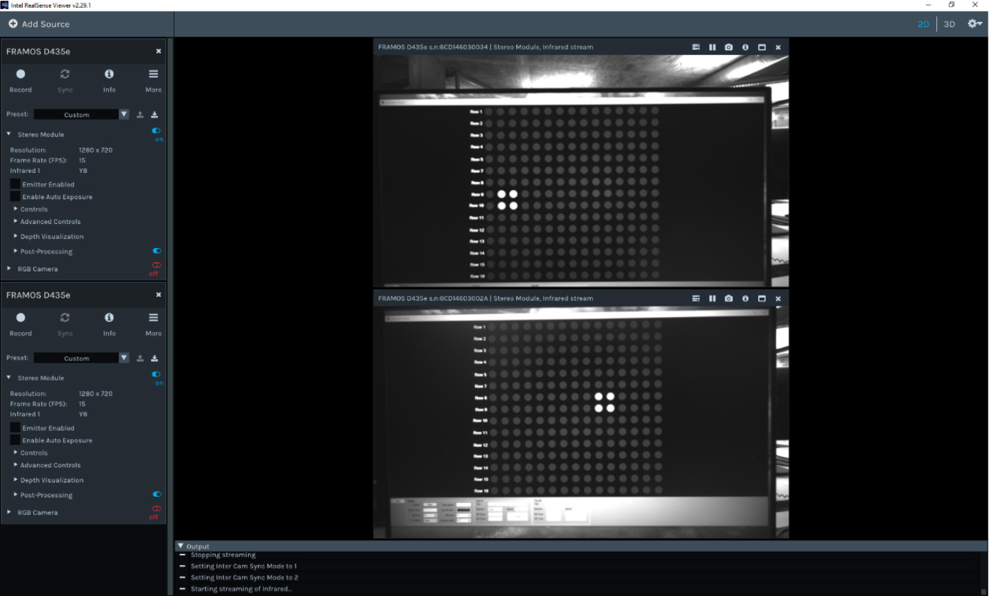
Figure 9 – Asynchronous Streams from two FRAMOS D435e Cameras#
Synchronous streams from two different cameras are presented in Figure 10. With one camera configured as a master, and one as a slave, the captured images show bright LEDs in the same position: starting in row 10, column 2.

Figure 10 – Synchronous Streams from two FRAMOS D435e Cameras#
References#
Revision History#
Date |
Version |
Changes |
|---|---|---|
2020-06-30 |
1.0.0 |
Initial release |
2021-07-15 |
1.1.0 |
Updated chapter “Hardware Configuration”; Updated “References” |
2021-10-15 |
1.2.0 |
Updated chapter “Setting Operating Mode”; Updated chapter “Hardware Validation” |
Table 5 – Revision History
Note
This document replaces and supersedes the application note “FRAMOS Industrial Depth Camera D435e - Multi-Camera Synchronization” v1.0.0.