
Multi Sensor Synchronization#
Introduction#
In the world of visual systems, taking two images at the same time involves a meticulous synchronization of precise signal timing. Many applications like Inspection systems, Stereo Vision, 3D cameras and Panorama stitching require and benefit from sensor triggering and synchronization.
Ideally a perfect multi-sensor synchronization would result in images that are taken and read at the same time from all sensors. This means all sensors shall run at the same FPS, and each frame is synchronized to a v-sync signal. This appnote and given examples assume all sensors operate at the same FPS, but their exposure times can be different as long as maximum exposure time is not exceeded.
However, a time difference between the synchronized sensors is practically inevitable. This difference can be within a few sensor clock cycles or within one horizontal line period of the sensor, depending on the synchronization mode.*
This application note discusses three synchronization modes in SONY Rolling Shutter sensors considering applications which require minimum delay between the captured images (Master-Slave Sync Mode), minimum signal connections between the sensors (Master-Master Sync Mode) or require the sensors to synchronize to external signals (External Sync Mode). Examples to achieve these synchronization modes using FRAMOS FSM:GO and FSM development kits and drivers are presented.
*Refer to Expected Synchronization Performance.
Theory#
This application note discusses three synchronization modes feasible with SONY rolling shutter sensors as stated in Appendix:
Master-Master synchronization
Master-Slave synchronization
External Synchronization
Master-Master Synchronization#
Applications which require interconnecting minimum number of signal lines between different sensors can benefit from the Master-Master synchronization mode.
In this mode, synchronization is achieved between different master sensors by interconnecting the sensors vertical sync signals (Figure 1). One master sensor operates in sync with its own local clock and outputs sync signals (via the XVS pin) to other master sensors for synchronization.
In FSM Ecosystem, using this mode the sensors readout timing can be synchronized within one horizontal line period (1H). From experience, the output images will have up to one line difference, regardless of the sensors using different or common clock (INCK) source. When sensors use different INCK sources, there can be a frame-to- frame phase drift. This frame-to-frame drift can be avoided using a common INCK source, there still will be a phase difference when starting a new image acquisition.
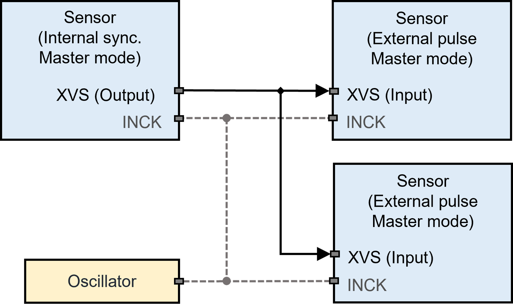
Figure 1. Master-Master Synchronization mode *
* Using common clock (INCK) source is optional.
Master-Slave Synchronization#
Applications that require minimum delay between the captured images can benefit from the Master-Slave Synchronization.
In this mode, slave sensors can be operated in sync with an inputting vertical and horizontal sync signal from an image sensor in master mode (Figure 2). The master sensor operates in sync with its local clock and outputs sync signals. The slave sensors are driven by inputting XVS and XHS signals.
In FSM Ecosystem, using this mode the sensors readout timing can be synchronized up to a few sensor clock periods. From experience, no difference in synchronization performance was observed when using a common clock source or difference clock sources for the sensors.
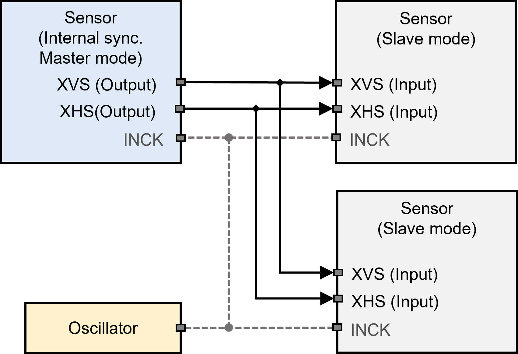
Figure 2. Master-Slave Synchronization Mode *
* Using common clock (INCK) source is optional.
External Synchronization#
Application that requires synchronizing image sensors with external signals can use external synchronization mode.
External Master Synchronization#
Master sensors can be synchronized using an external sync signal inputting through the XVS pin (Figure 3). Synchronization performance between the master sensors is expected to be like Master-Master mode (Refer to Master-Master Synchronization)
External Slave Synchronization#
Slave sensors can be synchronized by receiving horizontal and vertical sync signals from external source(s) (Figure 4). Sychronization performace between the slave sensors is expected to be like the Master-Slave mode (Refer to Master-Slave Synchronization).
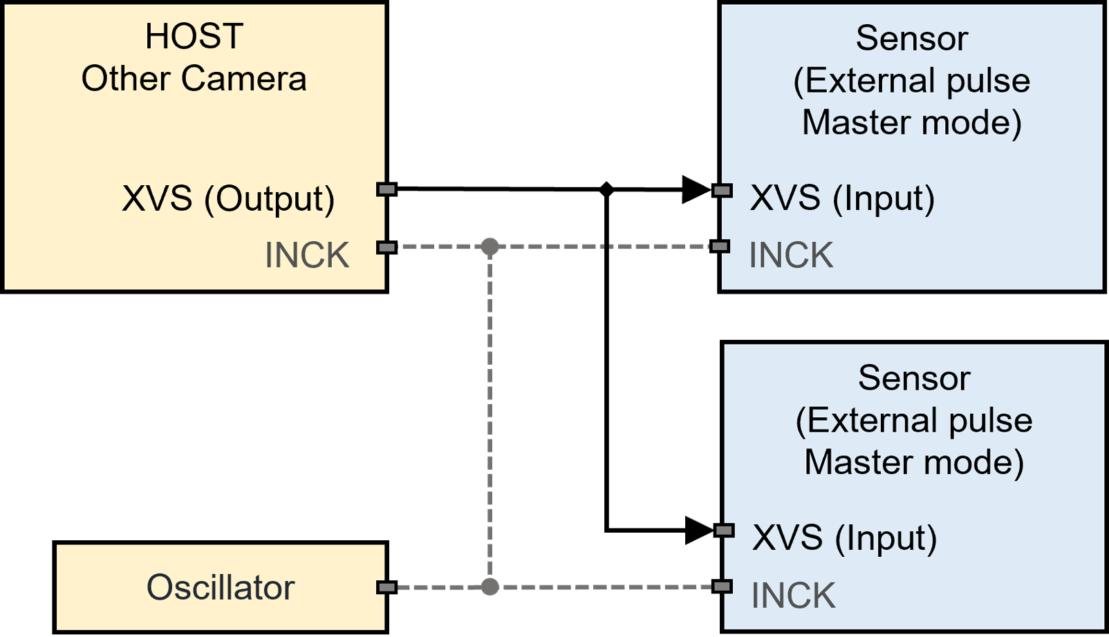
Figure 3. External Master Synchronization*
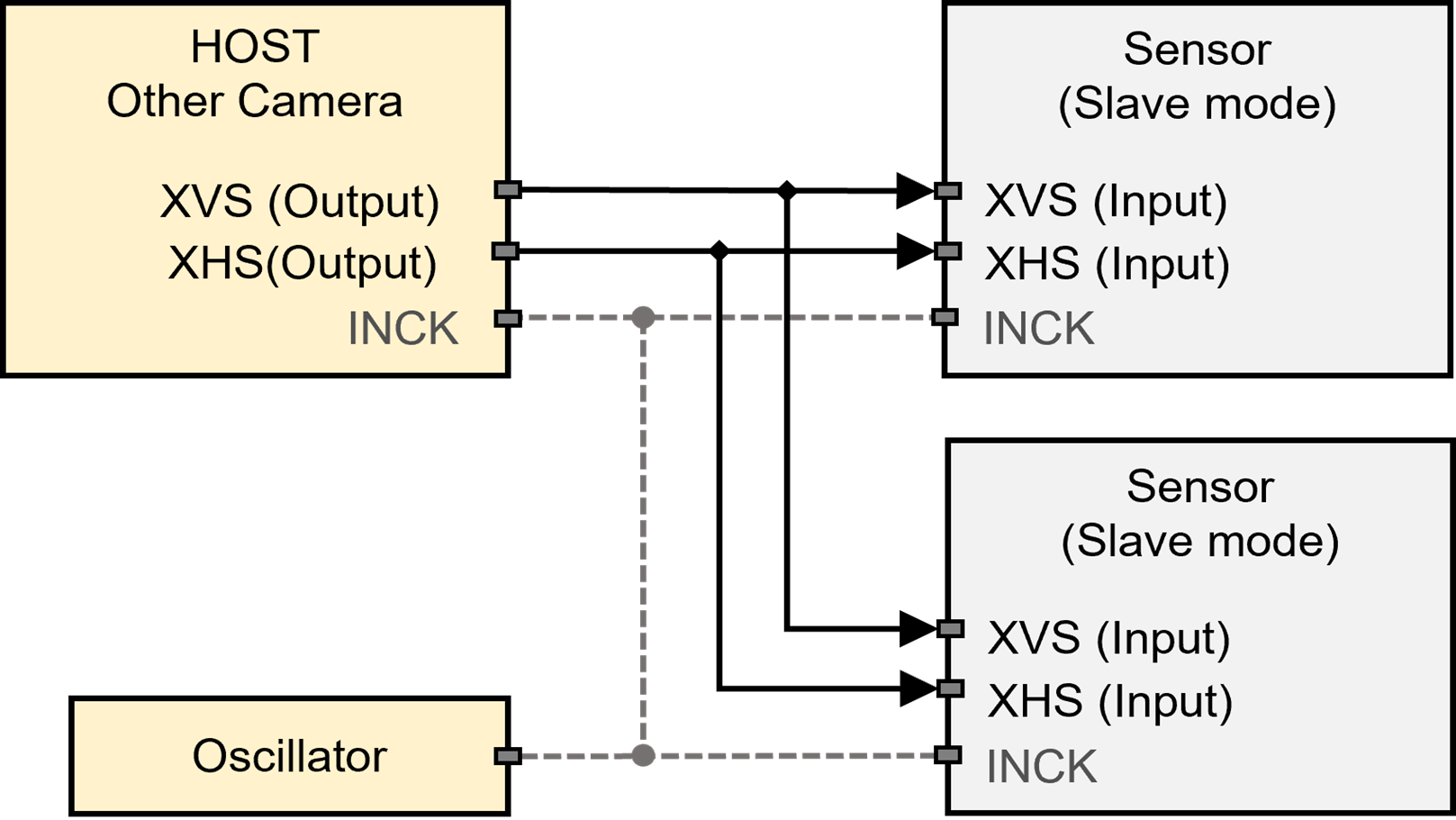
Figure 4. External Slave Synchronization*
* Using common clock (INCK) source is optional.
Expected Synchronization Performance#
The expected delay between master-master sync is up to one horizontal line time, or 1H time. The expected delay between master- slave sync is up to a few INCK clock cycles.
In the case of IMX678 and below examples, the INCK is 74.25MHz; each clock cycle is 13.47ns. Master-slave sync allows for synchronization within dozens of nanoseconds.
Horizontal line time is denoted in units of INCK cycles and is dependent on operation modes. For IMX678 12bit at 60fps, 1H period is 550 INCK cycles or 7.4μs. Thus, using master-master sync, there will be up to 7.4μs delay between the two sensors.
Please refer to sensor documentation for more details.
FSM Ecosystem Hardware Description#
Synchronization schemes (described in Theory) require interconnecting the sensors sync signals (XVS or XHS) between the sensors to be synchronized. In addition, to drive sensors in Slave mode managing the sensor’s XMASTER pin is required. This section provides details on managing these signals in the FSM Ecosystem.
FPA-4.A/AGX#
Supported platforms: Jetson AGX Xavier, Jetson AGX Orin
The sync signals (XVS or XHS) between the sensors connected to J5-J8 connectors, can be interconnected using the respective XVS (SW1) / XHS (SW2) switches on the FPA. An external XVS or XHS signal can be provided using the J1 connector.
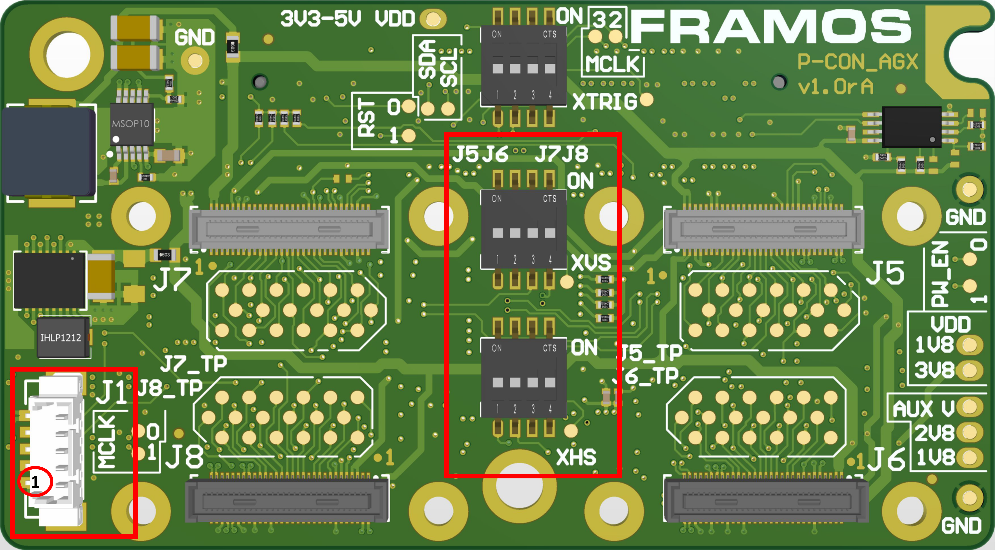
Figure 5. FPA-4.A/AGX: XVS, XHS switches and J1 connector
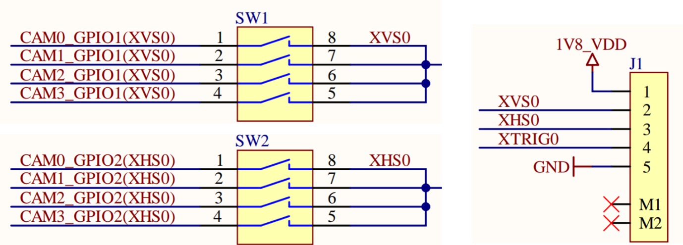
Figure 6. FPA-4.A/AGX: Schematics
FPA-A/P22-V2A#
Supported platforms: Jetson Orin Nano & Orin NX
In FPA-A/P22-V2A the XVS and/or XHS signals of different sensors can be connected by connecting the J4/J5 of one FPA to the J4/J5 of the other FPA.
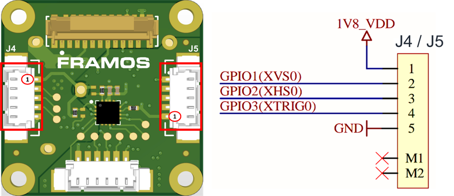
Figure 7. FPA-A/P22-V2A: J4/J5 Connectors
Slave Mode: FSM + FSA-FTx/A#
Supported sensor modules in Appendix.
Sensors can be switched between slave and master mode using the XMASTER pin. The XMASTER pin is managed in the FSM development kit using FSA’s DIP-switch pin 4 (Figure 8). Other registers are communicated by the sensor driver using I2C.
FSA SW PIN- 4 |
XMASTER |
Sensor Mode |
|---|---|---|
ON |
HIGH |
Slave |
OFF |
LOW |
Master |
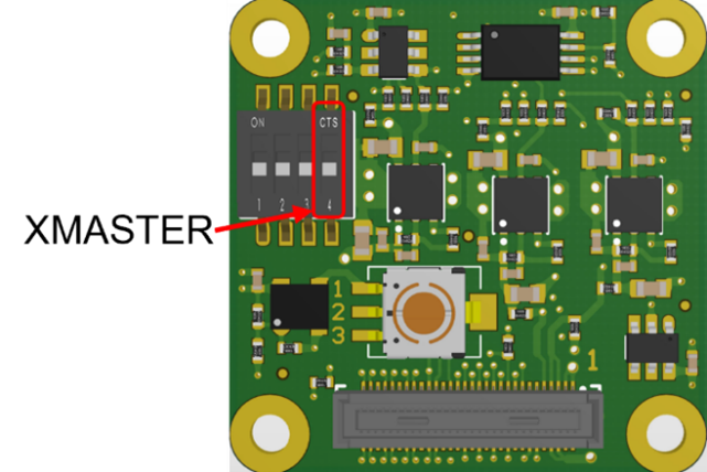
Figure 8. Slave mode selection in FSA-FTx/A
Slave Mode: FSM:GO#
Supported sensors modules in Appendix.
No hardware modifications are required for FSM:GO modules. Sensor’s XMASTER pin can be managed directly by the sensor driver using I2C.
Example 1: Master-Master Synchronization#
This section discusses the hardware setup and software settings required to synchronize sensor modules in Master-Master Synchronization in the FSM Ecosystem. It includes an example to synchronize one FSM:GO IMX678 and one FSM-IMX678 sensor module.
Prerequisite#
FRAMOS common driver and sensor driver installed.
Sensor Modules attached to the Jetson platform.
Hardware Setup: Jetson AGX Orin/Xavier platform#
Connect the XVS signals of the sensors to be synchronized using the XVS switch in FPA-4.A/AGX.
Example:
Figure 9 shows one FSM:GO-IMX678 connected to J5 and one FSM-IMX678 + FSA-FT26/A stacked setup connected to J7 connector of FPA-4.A/AGX. The corresponding XVS signals are interconnected by enabling the respective XVS switch pins in FPA-4.A/AGX.
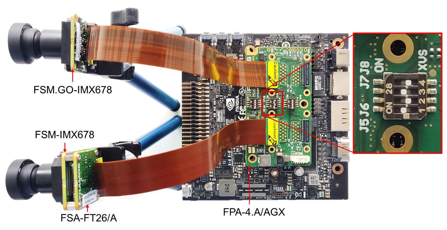
Figure 9. Master-Master Synchronization in Jetson AGX Xavier
Hardware Setup: Jetson Orin Nano/NX#
Connect the XVS signals using the J4/J5 connector in FPA-A/P22-V2A.
Example:
Figure 10 shows one FSM:GO-IMX678 and one FSM-IMX678 + FSA-FT26/A stacked setup attached to a Jetson Orin Nano Devkit through FPA-A/P22-V2A. The XVS signals between the FPA’s J4 connectors are connected using the FMA-CBL-MPB125-150/5 cable.

Figure 10. Master-Master Sync in Jetson Orin Nano
Software Settings#
The image sensor mode and synchronization can be set using the v4L controls. The control settings - operating mode and synchronizing function, should be modified as follows:
Control settings |
Sensor Internal Sync Master Mode |
Sensor External Sync Master Mode |
|---|---|---|
Operating mode |
Master Mode |
Master Mode |
Synchronizing function |
Internal Sync |
External Sync |
Table 1. Control Settings for Master-Master Synchronization Mode
Note: These control settings are valid for drivers released for AGX Xavier, AGX Orin and Orin Nano platforms with driver package v2.9.1
Example:
The v4l control settings can be modified using the prebuild LibSV example - display_image or using the v4l2-ctl tool.
Using LibSV display_image example to change driver settings:
|
|
|---|---|
|
b: External pulse master mode |


Figure 11. V4L Controls using LibSV display_image example.
Using the V4L2-CTL tool to change driver settings:
v4l2-ctl –d /dev/video0 –c operation_mode=0 –c
synchronizing_function=1v4l2-ctl –d /dev/video1 –c operation_mode=0 –c
synchronizing_function=2Using the V4L2-CTL tool to launch synchronized streams:
v4l2-ctl –d /dev/video0 –c operation_mode=0 –c synchronizing_function=1
–stream-mmap –stream-skip=10 –c bypass_mode=0 –verbose &
v4l2-ctl –d /dev/video1 –c operation_mode=0 –c
synchronizing_function=2
–stream-mmap –stream-skip=10 –c bypass_mode=0 –verbose
Example 2: Master-Slave Mode#
This section discusses the hardware setup and software settings required to synchronize sensor modules in Master-Slave mode in the FSM Ecosystem. It includes examples to synchronize one FSM:GO IMX678 and one FSM-IMX678 sensor module.
Prerequisite#
FRAMOS common driver and sensor driver.
XMASTER pin enabled in the FSA for slave sensors (Refer to Slave Mode: FSM + FSA-FTx/A). Only required for FSM+FSA stacked setup.
Connect the sensor modules to the Jetson platform.
Hardware Setup: Jetson AGX Orin/Xavier#
Connect the XVS signals of the sensors to be synchronized using the XVS switch in FPA-4.A/AGX.
Example:
Figure 12 shows one FSM:GO-IMX678 connected to J5 and one FSM-IMX678 + FSA-FT26/A stacked setup connected to J7 connector of FPA-4.A/AGX. The corresponding XVS & XHS signals are interconnected using the respective switches in FPA-4.A/AGX.
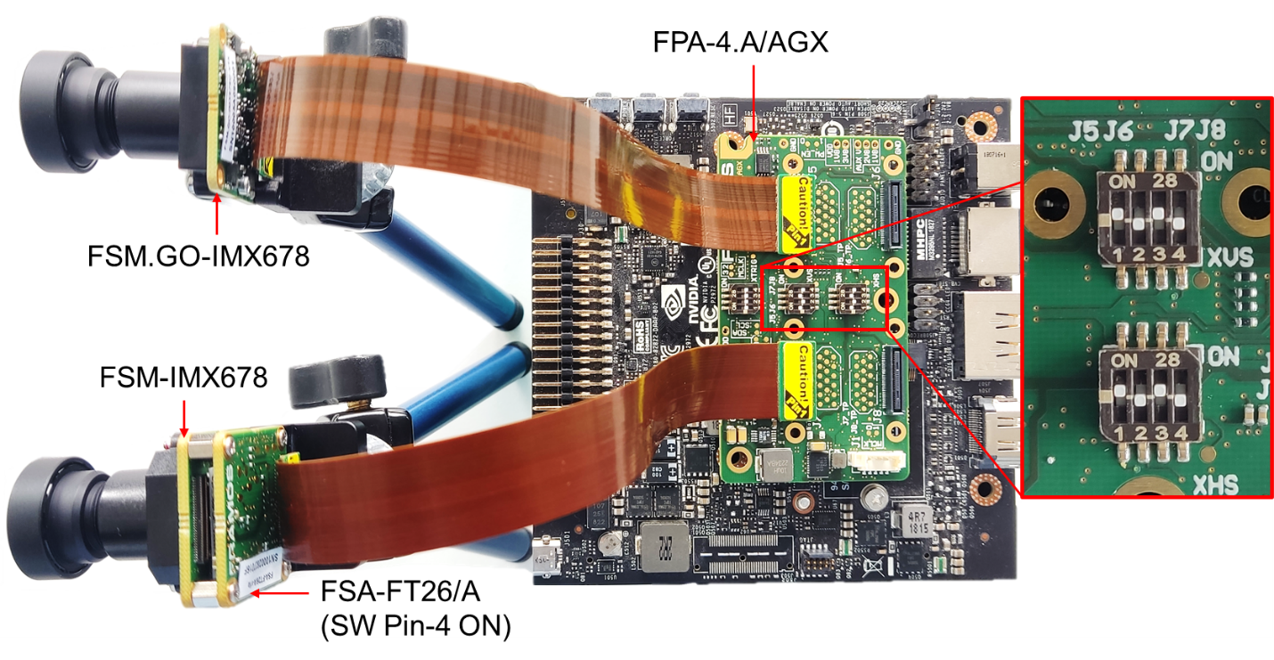
Figure 12. Master-Slave Sync in Jetson AGX Xavier
Hardware Setup: Jetson Orin Nano/NX#
Connect the XVS and XHS signals using the J4/J5 connector in FPA-A/P22-V2A.
Example:
Figure 13 shows one FSM:GO-IMX678 and one FSM-IMX678 + FSA-FT26/A stacked setup attached to a Jetson Orin Nano platform through FPA-A/P22-V2A. The XVS & XHS signals between the FPA’s J4 connectors are connected using the FMA-CBL-MPB125-150/5 cable.
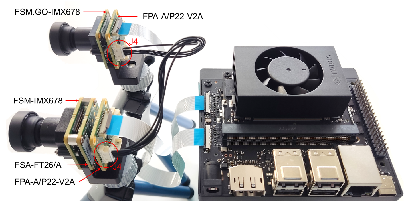
Figure13. Master-Slave Sync in Jetson Orin Nano
Software Settings#
The image sensor mode and synchronization can be set using the v4L controls. The control settings - operating mode and synchronizing function, should be modified as follows:
Control settings |
Sensor Internal Sync Master Mode |
Sensor Slave Mode |
|---|---|---|
Operating mode |
Master Mode |
Slave Mode |
Synchronizing function |
Internal Sync |
Internal or External Sync |
Table 2. Control Settings for Master-Slave Synchronization Mode
Note: These control settings are valid for drivers released for AGX Xavier, AGX Orin and Orin Nano/NX platforms with driver package v2.9.1
Example:
The v4l control settings can be modified using the prebuild LibSV example - display_image or using the v4l2-ctl tool.
Using LibSV display_image example to change driver settings:
|
|
|---|---|
|
|
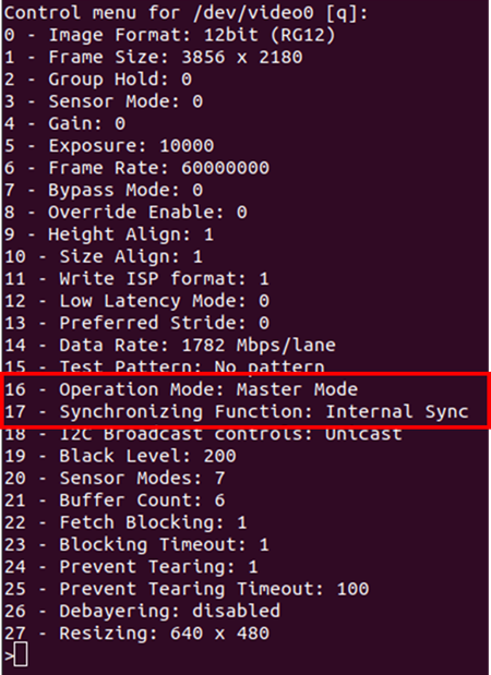
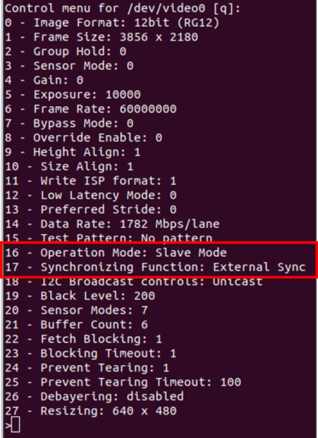
Figure 14. V4L Controls using LibSV display_image example.
The control settings can also be modified using the V4L2-CTL tool. Here is an example image acquisition pipeline:
Using the V4L2-CTL tool to change driver settings:
Master: v4l2-ctl –d /dev/video0 –c operation_mode=0 –c
synchronizing_function=1
Slave: v4l2-ctl –d /dev/video1 –c operation_mode=1 –c
synchronizing_function=2
Using the V4L2-CTL tool to launch synchronized streams:
v4l2-ctl –d /dev/video0 –c operation_mode=0 –c synchronizing_function=1
–stream-mmap –stream-skip=10 –c bypass_mode=0 –verbose &
v4l2-ctl –d /dev/video1 –c operation_mode=1 –c synchronizing_function=2
–stream-mmap –stream-skip=10 –c bypass_mode=0 –verbose
Example 3: External Master Sync Mode#
This section discusses the hardware setup and software settings required to synchronize sensor modules with an external XVS signal. The external signal can be generated using various sources (e.g. different sensors, pulse generator, microcontroller, FPGA, etc.) considering the generated XVS signal adheres to the electrical characteristics specified in the sensor documentation.
Prerequisite#
FRAMOS common driver, sensor driver and LibSV installed.
Sensor Modules attached to the Jetson platform.
Hardware Setup: Jetson AGX Orin/Xavier platform#
Enable the XVS switch in FPA-4.A/AGX for the sensors to be synchronized
Provide the external XVS signal through the J1 connector in FPA-4.A/AGX
Example: Figure 15 shows one FSM:GO-IMX678 connected to J5 and one FSM-IMX678 + FSA-FT26/A stacked setup connected to J7 connector of FPA-4.A/AGX. The external XVS signal is provided through the J1 connector and the XVS signals between the sensors are interconnected using the XVS (SW1) switch in FPA-4.A/AGX.
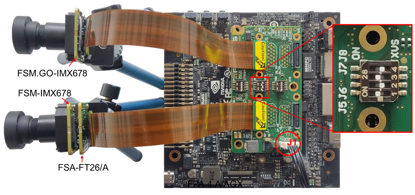
Figure 15. External Synchronisation in Jetson AGX Xavier
Hardware Setup: Jetson Orin Nano/NX#
Connect the XVS signals between the sensors to be synchronized using the J4/J5 connector in FPA-A/P22-V2A
Provide the external XVS signal through the connector J4/J5 in FPA-4.A/AGX
Example: Figure 16 shows one FSM:GO-IMX678 and one FSM-IMX678 + FSA-FT26/A stacked setup attached to a Jetson Orin Nano Devkit through FPA-A/P22-V2A. The external XVS signal is provided through the J4 connector and the XVS signals between the sensors are interconnected using the FPA’s J5 connectors using the FMA-CBL-MPB125-150/5 cable.
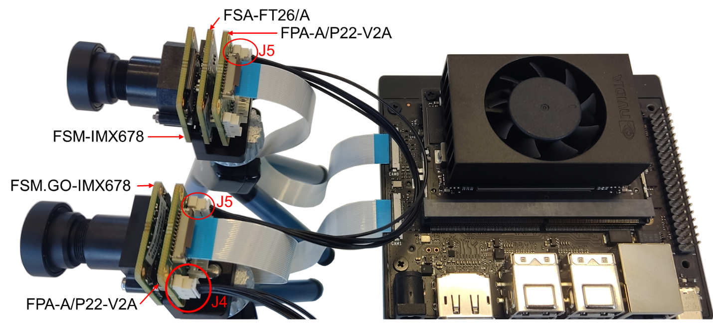
Figure 16. External Synchronization in Jetson Orin Nano
Software Settings#
The image sensor mode and synchronization can be set using the v4L controls. The control settings - operating mode and synchronizing function, should be modified as follows:
Control settings |
Sensor External Sync Master Mode |
|---|---|
Operating mode |
Master Mode |
Synchronizing function |
External Sync |
Table 3. Control Settings for External Master Synchronization Mode
Note: These control settings are valid for drivers released for AGX Xavier, Orin and Orin Nano platforms with Jetpack 5.1.2.
Example:
The v4l control settings can be modified using the prebuild LibSV example - display_image or using the v4l2-ctl tool.
Using LibSV display_image example to change driver settings:
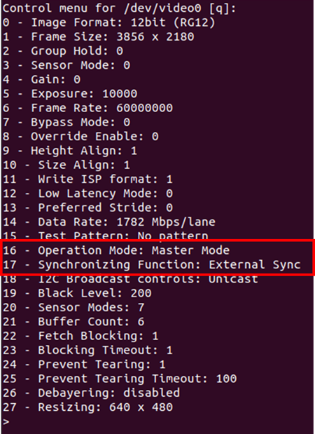
Figure 17. Control settings using display_image example
Using the V4L2-CTL tool to change driver settings:
v4l2-ctl –d /dev/video0 –c operation_mode=0 –c synchronizing_function=2
v4l2-ctl –d /dev/video1 –c operation_mode=0 –c synchronizing_function=2
Using the V4L2-CTL tool to launch synchronized streams:
v4l2-ctl –d /dev/video0 –c operation_mode=0 –c synchronizing_function=2
–stream-mmap –stream-skip=10 –c bypass_mode=0 –verbose &
v4l2-ctl –d /dev/video1 –c operation_mode=0 –c synchronizing_function=2
–stream-mmap –stream-skip=10 –c bypass_mode=0 –verbose
Appendix#
Supported Sensors#
This application note only provides examples (Refer to Example 1: Master-Master Synchronization, Example 2: Master-Slave Mode, Example 3: External Master Sync Mode) and hardware details (Refer to FSM Ecosystem Hardware Description) for using sensor modules with driver package v2.9.1 in Jetson AGX Orin/Xavier with FPA-4.A/AGX or Jetson Orin Nano/NX with FPA-A/P22. These supported sensors are summarized below:
Jetpack |
5.1.2 |
|
Driver Package |
v2.9.1 |
|
FPA |
FPA-4.A/AGX |
FPA-A/P22 |
Supported Sensors |
IMX715 |
IMX678 |
IMX678 |
IMX676 |
|
IMX676 |
IMX662 |
|
IMX675 |
||
IMX662 |
||
IMX585 |
||
IMX464 |
||
IMX415 |
||
IMX335 |
* Contact FRAMOS Support to check requirements or compatibility for older driver versions (< v2.9.1) and sensors outside the scope of this documentation.
Revision History#
Version 1.0