
Raspberry Pi 5#
This guide provides instructions to set up and use the Framos FPA-A/P22 adapter with the Raspberry Pi 5.
Requirements#
Hardware:
Raspberry Pi 5
Framos FPA-A/P22 Adapter (Included in the FPA-A/P22-V2A Devkit)
Framos Sensor Module (FSM:GO) , e.g., Sony IMXxxx
Check the Release Notes in the GitHub repo README.md file for supported FSM:GO models.
FMA-CBL-FFC22 Flex Cable (Included in FPA-A/P22-V2A Devkit)
Compatible power supply
Optional: Monitor, keyboard, and mouse
Software:
Internet connection for package installation
Access to the Framos RPI Drivers repository
Hardware Setup#
Scenario 1: PixelMate™ Flex Cable Connection
Requirements:
FSM:GO module (IMXxxx)
FPA-A/P22-V2A connector (Order Code: FPA-A/P22-V2A)
FMA-CBL-FFC22 Flex Cable (Order Code: FMA-CBL-FFC22)
Procedure:
Step 1: Connecting the FSM:GO Module to the FPA-A/P22-V2A
Orientation Check: Begin by confirming the orientation of the 60-pin PixelMate connectors on both the FSM:GO module and the FPA-A/P22-V2A. It is critical to align pin 1 of the FSM:GO connector with pin 1 on the FPA-A/P22-V2A to avoid any misalignment.
Connection: Carefully press the connectors together, ensuring that they are properly aligned and fully seated.

FSM:GO Module connected to the FPA-A/P22-V2A adapter.#
Step 2: Connecting the FPA-A/P22-V2A to the Raspberry Pi
Cable Attachment:
Attach one end of the FMA-CBL-FFC22 flex cable to the FPA-A/P22-V2A.
Make sure to use FFC Type A and verify the correct orientation of the cable before inserting it into the connector to avoid damaging the device.
Connecting to Raspberry Pi 5:
Connect the other end of the flex cable to one of the 22-pin CAM0 or CAM1 connectors on the Raspberry Pi 5 (located behind the Ethernet port).
Gently lift the brown latch on the Raspberry Pi connector to open it.
Insert the FFC cable with the reinforced side (typically blue) facing the latch side of the connector.
Ensure the contact pins are perpendicular to the connector plane before insertion.
Refer to the images below to distinguish between:
Open vs. closed connector latch (Figure 1)
Reinforced side vs. contact side of the cable (Figures 2 and 3)
Cable inserted into open vs. closed connector (Figures 4 and 5)
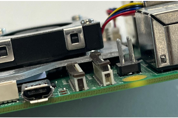
Figure 1: Example of a closed (secured) and open connector.#
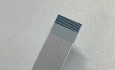
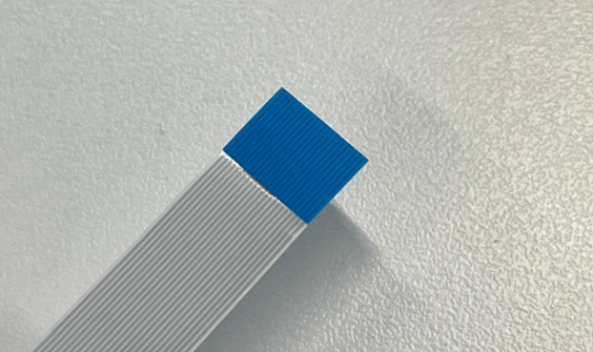
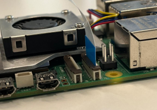
Figure 4: Inserted cable with closed, secured connection# |
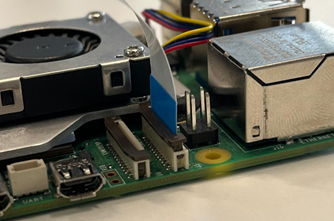
Figure 5: Inserted cable with open connector# |
Caution
Double-check connector orientation. Incorrect connector alignment may cause irreversible damage to both the FSM:GO module and Raspberry Pi 5.
Disconnect Power Before Connecting: Always ensure the Raspberry Pi is completely powered off and unplugged before making sensor connections. Even when powered off, the Pi can continue to supply 3.3V to peripherals, which may damage the sensor.
Scenario 2: GMSL Cable Connection
Required Materials:
FSM:GO module
FPA-A/P22-V2A Adapter
FFA-GMSL/SerDes-Kit
FMA-CBL-FFC22 Flex Cable
Compatible power supply
Step 1: Connecting the FFA-GMSL-Ser-V2A to the FSM:GO Module
Orientation Check: Align the 60-pin connectors of the FSM:GO module and the FFA-GMSL-Ser-V2A by matching pin 1 on both ends. This alignment is critical to prevent hardware damage.
Connection: Firmly press the connectors together until they securely engage.

FFA-GMSL-Ser-V2A connected to the FSM:GO module.#
Step 2: Connecting the FFA-GMSL-Des-V2A to the FPA-A/P22-V2A
Orientation Check: Ensure the 60-pin connectors of the FFA-GMSL-Des-V2A and the FPA-A/P22-V2A are correctly aligned (pin 1 to pin 1).
Connection: Press both connectors together firmly until fully seated.

FFA-GMSL-Des-V2A connected to the FPA-A/P22-V2A adapter.#
Step 3: Adding the GMSL Cable and Power Connection
GMSL Cable Connection: Connect the GMSL coaxial cable between the serializer and deserializer boards (FFA-GMSL-Ser-V2A ↔ FFA-GMSL-Des-V2A).
Power Connection: Plug the power cable into the FFA-GMSL-Des-V2A.
Important: Do not turn the power supply on yet. Power should only be enabled once all connections are verified.

GMSL cable and power connections.#
Step 4: Connecting to the Raspberry Pi 5
Attach the FMA-CBL-FFC22 flex cable between the FPA-A/P22-V2A and one of the 22-pin camera ports (CAM0/CAM1) on the Raspberry Pi 5.
Follow the same orientation and insertion steps outlined in the standard connection procedure above.
Caution
Incorrect orientation of connectors or cables may result in irreversible damage to both the FSM:GO module and Raspberry Pi 5.
Keep power disconnected until all components are fully and securely connected.
Software Installation#
To set up your Framos camera module on a Raspberry Pi, all required drivers, device tree overlays, and installation instructions are provided in the official Framos GitHub repositories:
Framos Raspberry Pi DriversThis repository contains:
- Device tree overlays for supported image sensor modules
- Installation scripts to simplify setup
- Configuration examples for different use cases
Make sure to review the Release Notes in the GitHub repository’s README.md file (available on the latest release branch) to verify that your specific sensor module is supported before proceeding with the installation.
Framos Libcamera StackThis repository is essential for enabling camera functionality via libcamera. It includes:
- Libcamera integration for Framos sensor modules
- ISP (Image Signal Processor) pipeline support
- Necessary configuration for capturing images and video using standard tools
Without this component, camera and ISP functionality will not work.
For the most up-to-date guidance and sensor compatibility, always refer to the repositories above.
Troubleshooting#
Issue |
Solution |
|---|---|
No image captured |
|
Camera not detected |
|
Image artifacts or noise |
|
Next Steps#
Explore Advanced Features: - Try out the capabilities of the
raspicamandlibcameralibraries for more control over camera functions.Driver Configuration: - Adjust driver settings to optimize parameters such as exposure and gain based on your application needs.
Integration: - Incorporate the camera module into your embedded applications or custom vision pipelines for enhanced functionality.