
External Trigger over GMSL for Global Shutter Modules#
Introduction#
This application note describes how to configure an external trigger setup over GMSL for FRAMOS’ global shutter camera modules.
The procedure outlined in this document uses Fast Trigger Mode. It’s also possible to operate the sensor using an external signal in Sequential Trigger Mode, depending on the application requirements.
In Fast Trigger Mode, the sensor operates in master mode. The XVS and XHS pins must be left unconnected as the sensor relies on internal timing signals. This simplifies the hardware setup compared to Sequential Trigger Mode since fewer external signals are required.
For additional details on the different modes and synchronization, refer to the Multi Sensor Synchronization: Global Shutter Appnote.
Required Hardware (Test Setup):
NVIDIA JEtson AGX Orin
FPA-4.A/AGX-V1A
FFA-GMSL-Ser-V2A/FFA-GMSL-Des-V2A (Serializer/Deserializer)
FSM:GO IMX900
FMA-CBL-MPB125-150/5
Signal generator (in this example, the FRAMOS HPSC4 Strobe Controller was used)
Pull-up resistor
1. HARDWARE CONFIGURATION#
1.1 FPA Board Switch Settings#
To route the trigger signal to the J6 camera port, configure the XTRIG switch block as shown in Figure 1 (highlighted at the top of the board).
Set the switches as follows:
Pin2: ON
Pins 1, 3, and 4: OFF
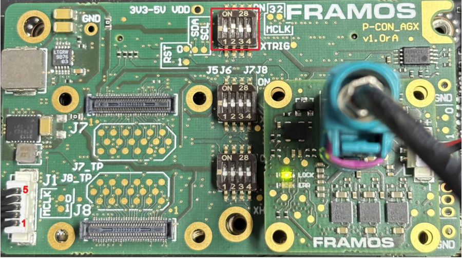
Figure 1: FPA-4.A/AGX: J1 and XTRIG
1.2 J1 Connector Pinout:#
Use the J1 connector with the FMA-CBL-MPB125-150/5 cable to interface with the external signal generator. If using an Open Collector output (like the HPSC strobe), use this pull-up connection:
Pin 1 (1.8V VDD): Connect to one side of the pull-up resistor.
Pin 4 (XTRIG0): COnnect to the other side of the resistor and to the Trigger Signal (+).
Pin 5 (GND): Connect to the Trigger Ground (-)..
Pull-up resistor: In this specific setup, a 4.7 kΩ resistor was used between Pin 1 and Pin 4 to stabilize the signal. Please note that the optimal resistor value may vary depending on your specific application.
The schematic of the J1 connection is shown in Figure 2.
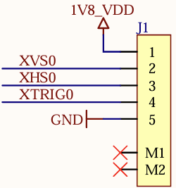
Figure 2: FPA-4.A/AGX J1 Schematic
2. SOFTWARE CONFIGURATION#
2.1 Identify the I2C bus#
Determine which I2C bus the sensor is connected to:
sudo dmesg | grep imx
Example output:
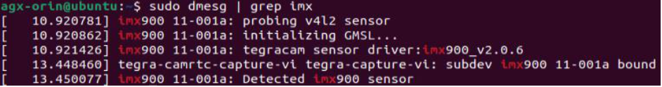
Figure 3: dmesg output
If the output shows 11-001a, your I2C bus is 11. Use this value in the commands below.
2.2 Create the GMSL GPIO Bridge#
The following commands create a virtual GPIO link through the GMSL devices. This allows the trigger signal received at the deserializer to be forwarded to the camera module.
Deserializer (MAX96792) - Port MFP9
sudo i2cset -y -f <bus> 0x6A 0x02 0xCB 0x83 i
sudo i2cset -y -f <bus> 0x6A 0x02 0xCC 0x18 i
sudo i2cset -y -f <bus> 0x6A 0x02 0xCD 0x58 i
Serializer (MAX96793) - Port MFP5
sudo i2cset -y -f <bus> 0x42 0x02 0xCD 0x84 i
sudo i2cset -y -f <bus> 0x42 0x02 0xCE 0x78 i
sudo i2cset -y -f <bus> 0x42 0x02 0xCF 0x58 i
Replace <bus> with your detected I2C bus number.
2.3 Sensor Software Configuration#
Configure the sensor to operate in Fast Trigger Mode. Using the LibSV display_image example to change driver settings (17, 20).
Global Shutter Mode: Fast Trigger
Operation Mode: Master
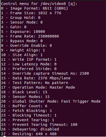
Figure 4: The Control Menu for the display_image LibSV example
Alternatively, use:
v4l2-ctl -d /dev/video0 -c operation_mode=0 -c global_shutter_mode=2
3. START STREAMING#
For validation, you can use acquire_image from libsv.
With the configuration described above, no frames will be received until an external trigger is applied.
Once the trigger signal is active, the output frame rate will follow the trigger frequency.
For example, applying a 30 Hz trigger signal will result in a 30 fps stream.
REFERENCES#
FRAMOS-Appnote, Multi Sensor Synchronization: Global Shutter