
IMX296x#
A 1.6MP Global Shutter optical sensor module with the Sony Pregius image sensor.
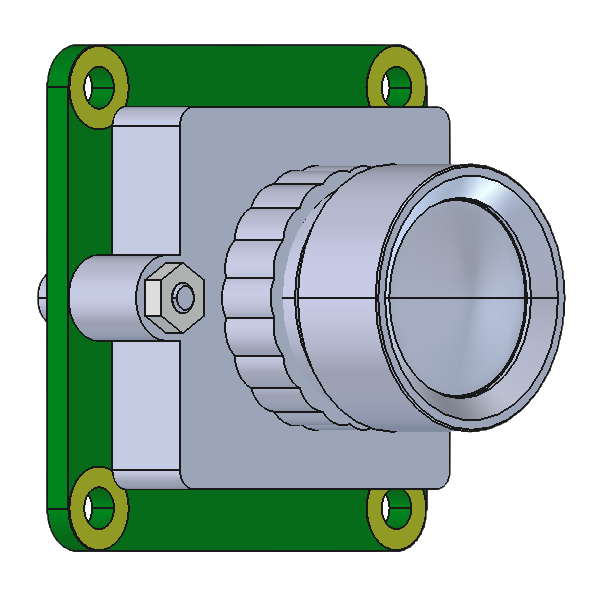
Product Specification - Overview#
Sensor Module#
Type |
Sony IMX296LLR/LQR |
|---|---|
Shutter Type |
CMOS Global Shutter |
Technology |
Pregius (Gen2) |
Spectrum |
Mono/Color |
Optical Format |
1/2.9” |
Pixel Size |
3.45 x 3.45 µm |
Resolution (max.) |
1456 x 1088 |
Framerate (max.)* |
60 FPS (1-Lane) |
Bit Depth* |
10 bit |
Communication |
I²C |
*Platform dependent`
Platform Support (Driver, ISP)#
NVIDIA |
Jetson Family (Orin, Nano) |
Supported JP/L4T Versions#
Version |
|
|---|---|
JetPack / L4T |
6.2.1 / 36.4.4 |
6.2 / 36.4.3 |
|
6.1 / 36.4 |
|
6.0 / 36.3 |
Interface Option(s)#
Data Interface |
MIPI CSI-2 v1.2 (D-PHY v2.1) |
GMSL3/2 (12Gbps, 6Gbps) |
Physical Interface |
PixelMate (60 pin) Micro Coax (50 pin) FFC (40 pin) (unshielded) P22 (22pin FPC, RPi5-Type) |
FAKRA (Single Coax) |
Power Supply |
DC (two voltages) |
Power over Coax (12V) |
Power Cons. (3.8V) |
525mW |
|
Power Cons. (1.8V) |
155mW |
|
Power Cons. (Max) |
680mW |
1200mW |
Mechanical Specification#
Dimensions [mm] |
Board: 26.5 (W) x 26.5 (D) (H): Lens depending |
Housing |
Optional, GMSL3 only |
Lens Mount |
M12 x 0.5 (var. options) |
Applications#
Barcode scanning
Drones - AGV and AGVs
Industrial robotics
Automated inspection
Environmental#
IP Rating |
Board: None |
Operating Temperature |
-30° to +75°C* |
Storage Temperature |
-40°to +85°C* |
Ambient Humidity |
Max 95% RH, non-condensing |
*Sensor module without lens, check Lens Options for configurations with Lens.
Order Code Scheme/Options#
FSM-IMX296-[CH]-[LM]-[L]-[FS][FD]-[IF]-[MH]-A1Q1#
CH: Chromaticy
C: Color
M: Monochrome
LM: Lens Holder (Optional)
M12: Lens Specific
M12G: 13 mm Height
M12K: 14,1 mm Height
L: Lens Type (Optional)
L80A: 80° HFOV (LM: M12, M12H)
FS: Focusing Service (Optional)
FCS: Center Focusing (L: Required)
FD: Focusing Distance
HYP: Hyperfocal Distance
xxxx: Custom Distance in mm (FS: Required)
IF: Interface (Mandatory)
PM: PixelMate (60 pin)
MC50A: MicroCoax (50 pin)
FFC40A: Flat-Flex Cable (40 pin)
GMSL3A: GMSL3 (FAKRA, Single Coax)
P22A: FPC Cable (22 pin)
Lens Options#
Module Specification#
Type (Code) |
L80A |
Field of View [°] |
|
Horizontal |
80 |
Vertical |
64 |
Diagonal |
94 |
Aperture (F-Number) |
F/2.2 |
Optical Filter |
IRC@660 (±10nm) |
Mount Thread |
M12 x 0.5 |
Mating Mount (PN) |
Lens Matched |
Temperature Range |
-40°to +85°C* |
Sensor Coverage |
|
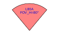
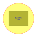
*Image tuning and assembly are performed at 25°C. Temperature variations may affect performance and focus.`
Lens Specification#
Type (Code) |
L80A |
Lens Type (PN) |
FLP-HM-029- 07-V-00 |
Focal length [mm] |
2.87 |
Min. Object Distance [m] |
0.15 |
Hyperfocal Distance [m] |
0.55 |
Max. Image Circle [mm] |
7.43 |
Back Focal Length [mm] |
3.49 |
Distortion [%] |
+3.9 (F-Tan-Theta) |
Rel. Illumination [%] |
62 |
Max. CRA [°] |
15.9 |
TTL [mm] |
33.62 |
Construction |
Hybrid |
Lens Barrel Material |
Plastic |
Focusing Service and Focusing Distance#
Specification#
Description |
No Focusing 1 |
Focusing to Hyperfocal |
Focusing to Custom Distance |
|---|---|---|---|
Type (Code) |
NA |
FCSHYP |
FCS[FD] |
Focus Distance[mm] |
NA |
Hyperfocal Distance [HYP]2 |
Custom Focus Distance [FD]3 |
Focus Target |
NA |
Virtual Image (Collimator) |
Virtual Image (Collimator) |
Focus Area 4 |
NA |
Image Center |
Image Center |
Lens Fixation |
NA |
Permanent (Epoxy) |
Permanent (Epoxy) |
1Lens is properly screwed into the lens mount without focusing and fixation.
2Please see “Hyperfocal Distance [m]” in Focusing Specifications table.
3Please see “Min. Object Distance [m]” to infinity in Focusing Specifications table.
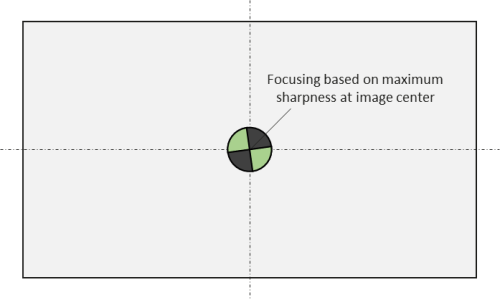
4Please see Figure 3.1 below showing the virtual target at image center as the focus area.
Focus Area#
Lens Mount Options#
Specification#
Type (Code) |
M12 (Default) |
M12G |
M12K |
|---|---|---|---|
Type (PN) |
Lens Matched |
FLA-MH-M- 13022-00 |
FLA-MA-M -14122-02 |
Thread Type |
M12 x 0.5 |
M12 x 0.5 |
M12 x 0.5 |
Height [mm] |
13 |
14.1 |
|
Material |
Plastic |
Plastic |
|
Appearance [Color] |
Black |
Black |
Black |
*Lens Matched, details in Lens Options and Mechanical Drawings.
Interface Options#
Type (Code) |
PM |
MC50A |
FFC40A |
GMSL3A |
P22A |
|---|---|---|---|---|---|
Description |
PixelMate |
Micro-Coax |
Flat-Flex Cable |
GMSL/SerDes |
FPC/FFC |
FSM Integration |
Default FSM Interface |
Adapter Board (Piggyback) |
Adapter Board (Piggyback) |
Adapter Board (Piggyback) |
Adapter Board (Piggyback) |
Interface Standard |
FRAMOS PixelMateC |
Proprietary |
Proprietary |
GMSL, FAKRA Coaxial |
Raspberry Pi 5 , Jetson Nano / NX Compatible |
Connector Type |
Hirose DF40C-60 DP-0.4V(51) |
I-PEX 20 525-050E-02 |
Molex 5051104091 |
Amphenol RF 2FA1 -NZSP-PCBB6 |
Hirose FH12-22 S-0.5SVA(54) |
Pin Count [#] |
60 |
50 |
40 |
1+GND |
22 |
Pin Pitch [mm] |
0.4mm |
0.4mm |
0.5mm |
0.5mm |
|
Locking Style |
Self - locking |
Mechanical locking |
Mechanical locking |
Mechanical locking |
Mechanical locking |
Shielding |
Yes |
Yes |
No |
Yes |
Yes |
Power Supply [V] |
3V8, 1V8 |
3V8, 1V8 |
3V8, 1V8 |
12V (Power over Coax) |
3V3 |
Data Lanes /Bandwidth |
4-Lanes, 2.5 Gbps (ea.) |
4-Lanes, 2.5 Gbps (ea.) |
4-Lanes, 2.5 Gbps (ea.) |
1-Line at 12Gbps (10Gbps Effective) |
4-Lanes, 2.5 Gbps (ea.) |
Mating Connector |
Hirose DF40C-60 DS-0.4V(51) |
I-PEX 20 525-050E-02 |
Molex 5051104091 |
Amphenol RF 2FA1 -NZSP-PCBB6 |
Hirose FH12-22 S-0.5SVA(54) |
Mating Cable(s) |
FMA- FC-150/60 |
FMA-CB L-MC50-0.3m |
Molex 0150200440 |
FMA-CB L-FAK.LD302 |
FMA-CBL-F FC22-0.2m |
Receiver Boards |
Various FPAs |
FFA-MC50/A |
FFA-FFC40/A |
FFA- GMSL-DES-V2 |
Pinouts#
Warning
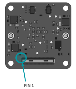
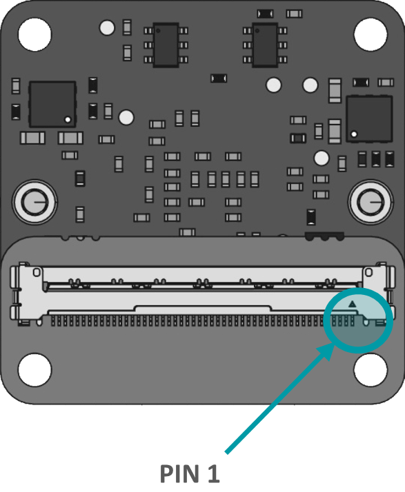
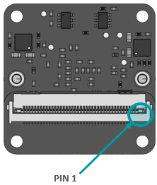
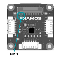
Pin 1 is identified on the board. Orient accordingly, paying close attention to the pin number in reference to the locater view illustrated below. Failure to align correctly will cause permanent damage.
PixelMate:#
Type: Hirose DF40C-60DP-0.4V(51) |
Pinout |
Pinout |
Pinout |
Pinout |
||||
|---|---|---|---|---|---|---|---|---|
|
1 |
3V8_VDD |
16 |
NC |
31 |
XTRIG |
46 |
NC |
2 |
1V8_VDD |
17 |
NC |
32 |
TOUT0 |
47 |
NC |
|
3 |
3V8_VDD |
18 |
SDO |
33 |
NC |
48 |
NC |
|
4 |
1V8_VDD |
19 |
NC |
34 |
NC |
49 |
GND |
|
5 |
NC |
20 |
TOUT1 |
35 |
NC |
50 |
GND |
|
6 |
NC |
21 |
SCK_SCL |
36 |
NC |
51 |
D_DATA_0_N |
|
7 |
NC |
22 |
NC |
37 |
GND |
52 |
NC |
|
8 |
NC |
23 |
XCE |
38 |
GND |
53 |
D_DATA_0_P |
|
9 |
NC |
24 |
NC |
39 |
MCLK_0 |
54 |
NC |
|
10 |
NC |
25 |
XVS |
40 |
NC |
55 |
GND |
|
11 |
GND |
26 |
TOUT2 |
41 |
NC |
56 |
GND |
|
12 |
GND |
27 |
SDI_SDA |
42 |
NC |
57 |
NC |
|
13 |
GND |
28 |
NC |
43 |
GND |
58 |
D_CLK_0_P |
|
14 |
GND |
29 |
XHS |
44 |
GND |
59 |
NC |
|
15 |
RST_0 |
30 |
NC |
45 |
NC |
60 |
D_CLK_0_N |
MC50:#
Type: I-PEX 20525-050E-02 |
Pinout |
Pinout |
Pinout |
Pinout |
||||
|---|---|---|---|---|---|---|---|---|
|
1 |
GND |
14 |
NC |
27 |
TOUT2 |
40 |
NC |
2 |
D_CLK_0_N |
15 |
NC |
28 |
XVS |
41 |
NC |
|
3 |
D_CLK_0_P |
16 |
GND |
29 |
NC |
42 |
NC |
|
4 |
GND |
17 |
MCLK_0 |
30 |
XCE |
43 |
NC |
|
5 |
NC |
18 |
NC |
31 |
SCK_SCL |
44 |
NC |
|
6 |
NC |
19 |
NC |
32 |
TOUT1 |
45 |
GND |
|
7 |
GND |
20 |
NC |
33 |
NC |
46 |
1V8_VDD |
|
8 |
NC |
21 |
NC |
34 |
SDO |
47 |
1V8_VDD |
|
9 |
NC |
22 |
TOUT0 |
35 |
NC |
48 |
GND |
|
10 |
GND |
23 |
XTRIG |
36 |
NC |
49 |
3V8_VDD |
|
11 |
D_DATA_0_P |
24 |
NC |
37 |
RST_0 |
50 |
3V8_VDD |
|
12 |
D_DATA_0_N |
25 |
XHS |
38 |
GND |
|||
13 |
GND |
26 |
SDI_SDA |
39 |
NC |
FFC40:#
Type: Molex 5051104091 |
Pinout |
Pinout |
Pinout |
Pinout |
||||
|---|---|---|---|---|---|---|---|---|
|
1 |
GND |
11 |
D_DATA_0_P |
21 |
XTRIG |
31 |
NC |
2 |
D_CLK_0_N |
12 |
D_DATA_0_N |
22 |
XHS |
32 |
NC |
|
3 |
D_CLK_0_P |
13 |
GND |
23 |
XVS |
33 |
NC |
|
4 |
GND |
14 |
NC |
24 |
SDI_SDA |
34 |
GND |
|
5 |
NC |
15 |
NC |
25 |
SCK_SCL |
35 |
1V8_VDD |
|
6 |
NC |
16 |
GND |
26 |
NC |
36 |
1V8_VDD |
|
7 |
GND |
17 |
MCLK_0 |
27 |
RST_0 |
37 |
GND |
|
8 |
NC |
18 |
GND |
28 |
NC |
38 |
3V8_VDD |
|
9 |
NC |
19 |
NC |
29 |
NC |
39 |
3V8_VDD |
|
10 |
GND |
20 |
NC |
30 |
NC |
40 |
GND |
GMSL3A:#
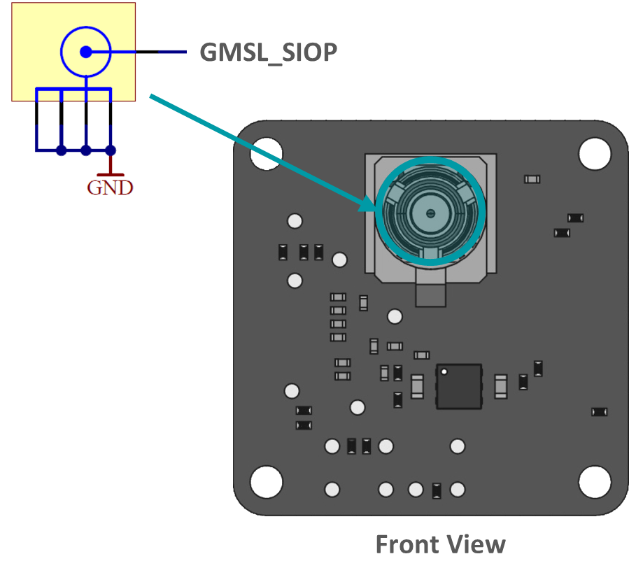
Type: 2FA1-NZSP-PCBB6 |
Pinout |
|
|---|---|---|
|
1 |
GMSL_SIOP |
2 |
GND |
P22A:#
Type: Hirose FH 12-22S-0.5SVA(54) |
Pinout |
Pinout |
||
|---|---|---|---|---|
|
1 |
GND |
12 |
D_DATA_2_P |
2 |
D_DATA_0_N |
13 |
GND |
|
3 |
D_DATA_0_P |
14 |
D_DATA_3_N |
|
4 |
GND |
15 |
D_DATA_3_P |
|
5 |
D_DATA_1_N |
16 |
GND |
|
6 |
D_DATA_1_P |
17 |
IS_RST_0 |
|
7 |
GND |
18 |
MCLK_IN |
|
8 |
D_CLK_0_N |
19 |
GND |
|
9 |
D_CLK_0_P |
20 |
I2C_SCL_IN* |
|
10 |
GND |
21 |
I2C_SDA_IN* |
|
11 |
D_DATA_2_N |
22 |
3V3_VDD |
*LVCMOS33 (3.3V) logic is to be applied!
The three Molex Microblade connectors (left, bottom, right sides) provide access to several other sensor signals – like XVS, XHS, XTRIG and TOUT - that can be used for synchronization of multiple sensors to each other or to an external source (i.e. a microcontroller). Check the online documentation about FPA-A/P22-V2 for more details.
Signal Description#
3V8_VDD I/O Type: Power Function: 3.8V power supply Connected to: LDO_IC I/O Standard: - I/O State: - DC Charact.: 3.7V-5.1V, max. 0.3A per line* |
1V8_VDD I/O Type: Power Function: 1.8V power supply Connected to: LDO_IC I/O Standard: - I/O State: - DC Charact.: 1.7V-1.9V, max. 0.3A per line* |
RST_0 I/O Type: IN Function: Image sensor Reset 0 line (default one) Connected to: Reset_IC I/O Standard: LVCMOS18 I/O State: Normal: High, Reset: Low DC Charact.: VILmax=0.36V, VIHmin=1.44V |
SDO I/O Type: OUT Function: SPI data output Connected to: Image sensor I/O Standard: LVCMOS18 I/O State: - DC Charact.: VOLmax=0.4V, VOHmin=1.4V |
SCK_SCL I/O Type: IN/OUT Function: SPI/I2C clock line Connected to: Image sensor; pullup option available but not enabled by default I/O Standard: LVCMOS18 I/O State: - DC Charact.: VILmax=0.36V, VIHmin=1.44V |
SDI_SDA I/O Type: IN/OUT Function: SPI data input / I2C data line Connected to: Image sensor; pullup option available but not enabled by default I/O Standard: LVCMOS18 I/O State: - DC Charact.: VILmax=0.36V, VIHmin=1.44V |
XCE I/O Type: IN Function: SPI XCE pin Connected to: Image sensor, 1k pull-up resistor soldered by default to put image sensor in I2C mode I/O Standard: LVCMOS18 I/O State: - DC Charact.: VILmax=0.36V, VIHmin=1.44V |
XTRIG I/O Type: IN Function: Image sensor trigger input Connected to: Image sensor’s XTRIG line I/O Standard: LVCMOS18 I/O State: - DC Charact.: VILmax=0.36V, VIHmin=1.44V |
XVS/XHS I/O Type: IN/OUT Function: Image sensor synchronization signals Connected to: Image sensor’s XVS and XHS lines, 10k pullups I/O Standard: LVCMOS18 I/O State: - DC Charact.: VOLmax=0.4V, VOHmin=1.4V |
TOUT0/1/2 I/O Type: OUT Function: Pulse output signals Connected to: Image sensor, no pullup/pulldown I/O Standard: LVCMOS18 I/O State: - DC Charact.: VOLmax=0.4V, VOHmin=1.4V |
MCLK_0 I/O Type: IN Function: Master clock for image sensor Connected to: Image sensor’s clock line; by default driven from oscillator I/O Standard: LVCMOS18 I/O State: - DC Charact.: VILmax=0.36V, VIHmin=1.44V |
|
D_DATA_0_P/N I/O Type: OUT Function: MIPI-CSI2 data lane D0 Connected to: DOP0/DOM0 pins on image sensor I/O Standard: MIPI D-PHY I/O State: - DC Charact.: - |
D_CLK_0_P/N I/O Type: OUT Function: MIPI-CSI2 clock pair CLK0 Connected to: DCKP/DCKM pins on image sensor I/O Standard: MIPI D-PHY I/O State: - DC Charact.: - |
* General range of what the connector pin can physically carry, may vary on a case-by-case basis.
I2C Address Configuration (SLAMODE)#
SLAMODE2 |
SLAMODE1 |
SLAMODE0 |
1ˢᵗ I2C Address |
2ⁿᵈ I2C Address |
|---|---|---|---|---|
0 |
0 |
0 |
0x1A |
0x36 |
0 |
0 |
1 |
0x1A |
0x37 |
0 |
1 |
0 |
0x1A |
0x38 |
0 |
1 |
1 |
0x1A |
0x39 |
1 |
0 |
0 |
0x1A |
0x3A |
1 |
0 |
1 |
0x1A |
0x3B |
1 |
1 |
0 |
0x1A |
0x3C |
1 |
1 |
1 |
0x1A |
0x3D |
Note
The FRAMOS driver uses the 1ˢᵗ I2C Address (
0x1A) by default.Users can configure additional SLAMODE signals via DIO (Digital Input/Output) pins from the host to set a unique 2ⁿᵈ I2C Address.
When using multiple sensors on the same host, ensure each sensor is assigned a unique 2ⁿᵈ I2C Address to avoid conflicts.
Power-On Sequencing#
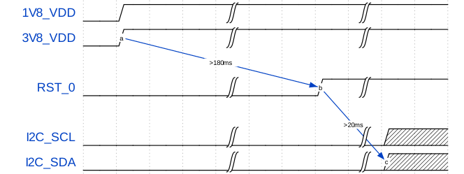
For correct function, the host system must follow the timing below to properly power up or reset the module.
3V8_VDD should be generated after 1V8_VDD, or, ideally at the same time. The RST_0 pin should be low after powering up PixelMate voltage rails > 180 ms.
Legend#
Times and voltages which are represented in the above figure are as follows:
3V8_VDD - 3V8 voltage supply from host
1V8_VDD - 1V8 voltage supply from host
RST_0 - reset signal driven from the host
I2C_SCL - I2C Clock
I2C_SDA - I2C Data
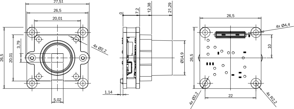
Mechanical Drawings#
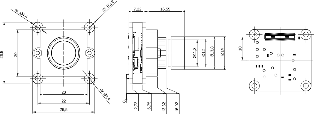
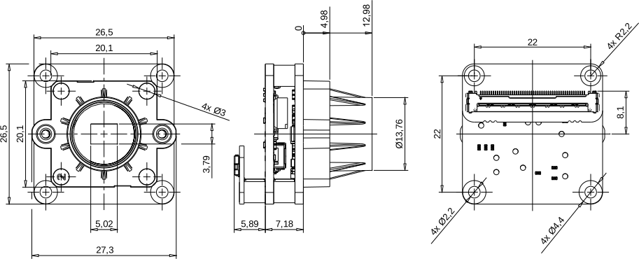
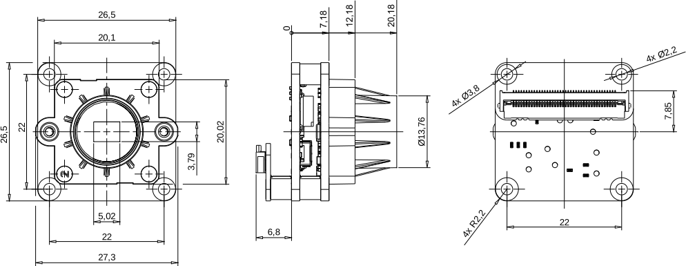
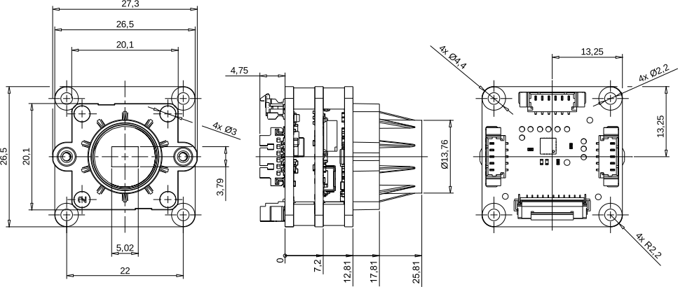
The following chapter contains the measured drawings split into the core segments of the product.
Bare Sensor Module
with Mount
with Mount + Lens
with Interface Adapter
All measures refer to the backside of the sensor module PCB and, this way, allow the acquisition of the overall measures. Units of measurement are expressed in milimeters [mm]².
Sensor Module (Bare FSM)#
Interface: PixelMate™#
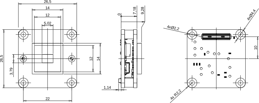
*1 - clearance area
*2 - holes size tolerance +/-0,1mm
*3 - holes position tolerance +/-0,1mm
*4 - connector size & alignment tolerance (X,Y,Z,tilt) +/-0,20mm
*5 - center of active sensor area is aligned with center of sensor board area
sensor active area size & alignment tolerance (X,Y,Z,tilt) +/-0.25mm
2 All mechanical components of the module assembly are subject to form and dimensional tolerances; therefore, sufficient mechanical clearance must be provided during integration, particularly around the lens and lens mount. The placement of electrical components on the PCBs (excluding connectors) may change without prior notice.
FSM with Mount#
M12G: 13 mm Height
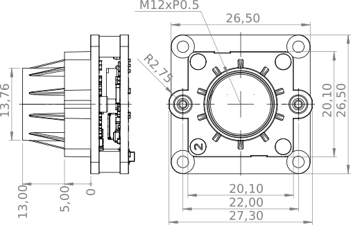
M12K: 12.5 mm Height
FSM with Mount + Lens#
L80A: 80° HFOV (LH: M12)
FSM with Interface Adapter#
PM: See Bare Sensor Module#
Note
Interface adapters fixed with screws for transport, mounting screws not included in product photos and drawings.
MC50A: MicroCoax (50 pin)#
FFC40A: Flat-Flex Cable (40 pin)#
GMSL3A: (FAKRA, Single Coax)#
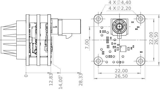
P22A: Flat-Printed Circuit Cable (22 pin)#
Platform Compatibility and Software Support#
The FSM:FSA camera module comes with ongoing and off-the-shelf driver support for the latest NVIDIA Jetson Developer Kits and rudimentary ISP tuning working well in office environments. Further compute platforms like NXP, Qualcomm or Raspberry Pi are physically compatible, leveraging our modular adapter ecosystem. Drivers are supported on a per project basis, as well as comprehensive ISP configurations, delivering the best image under any conditions. Implemented sensor and ISP features, as well as the archived performance, are directly related to the capabilities of each processing platform and the BSP maintained by its vendor. GitHub repository for all available driver releases as well as our online documentation for any hardware references.