IMX06Ax#

A 50MP/8K optical sensor module with a cutting edge Sony sensor in an industrial package.
Product Specification - Overview#
Sensor Module#
Type |
Sony IMX06A-AJIR-J/AMR-J |
Shutter Type |
CMOS Rolling Shutter |
Technology |
Quad-Bayer RGGB |
Spectrum |
Color (RGGB, Quad Bayer), Monochrome |
Optical Format |
1/0.98” |
Pixel Size |
1.6 x 1.6 µm |
Resolution (max.) |
8192x6144 (8K/50MP) |
Framerate (max.) * |
10bit: 15 FPS |
Bit Depth * |
10 bit |
Clock |
24 MHz (On board) |
Communication |
I2C |
*Platform dependent
Platform Support (Driver, ISP)#
NVIDIA |
Jetson Family (Orin) |
Supported JP/L4T Versions#
Version |
|
|---|---|
JetPack / L4T |
6.2.1 / 36.4.4 |
Check out our GitHub repository for all available driver releases as well as our online documentation for any hardware references.
Interface Option(s)#
Data Interface |
MIPI CSI-2 |
|---|---|
Interface Specifications |
4-Lane D-PHY (v2.1) |
Physical Interface |
PixelMate (60 pin) |
Communication |
I²C |
Power Supply |
Two Rails (3.8V, 1.8V) |
Mechanical Specification#
Dimensions [mm] |
30.5mm x 30.5 mm (H): Lens Depending |
|---|---|
Housing |
None / Boardlevel |
Lens Mount |
|
Applications#
Drones - AGV and AGVs
Streaming and conferencing
Sport analytics
Mapping, digital twins
Environmental#
IP Rating |
None |
|---|---|
Operating Temperature |
-20° to +85°C* |
Performance Guarantee |
0 to 60°C* |
Storage Temperature |
-40°to +85°C* |
Ambient Humidity |
Max 95% RH, non-condensing |
*Sensor module without lens, check Lens Options for configurations with Lens.
Order Code Scheme/Options#
FSM:GO-IMX06A[CH]-[LM]-[L]-[IF]-A1Q1#
CH: Chromaticy
C: Color
M: Monochrome
LM: Lens Holder (Optional)
M22A: Lens Matched
L: Lens Type (Optional)
L81A: 81° HFOV (LM: M22A)
L122A: 122° HFOV (LM: M22A)
IF: Interface (Mandatory)
PM: PixelMate (60 pin)
Lens Options#
Module Specifications#
Lens Type (PN) |
L81A |
L122A |
Field of View [°] |
|
|
Horizontal |
81 |
122 |
Vertical |
64 |
93 |
Diagonal |
94 |
148 |
Aperture (F-Number) |
F/2.8 |
F/2.8 |
Optical Filter |
IRC@650 (±10nm) |
IRC@650 (±10nm) |
Mount Thread |
M22 x 0.5 |
M22 x 0.5 |
Mating Mount (PN) |
Lens Matched |
Lens Matched |
Temperature Range |
-40° to +85°C* |
-40° to +85°C* |
Sensor Coverage |
|
|
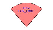
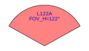
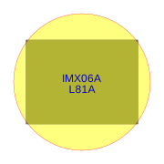
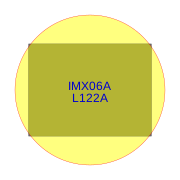
*Image tuning and assembly are performed at 25°C. Temperature variations may affect performance and focus.
Lens Specification#
Lens |
L81A |
L122A |
|---|---|---|
Focal length [mm] |
8.3 |
5.48 |
Min. Object Distance [m] |
N/A |
N/A |
Hyperfocal Distance [m] |
7.7 |
3.34 |
Max. Image Circle [mm] |
16 |
16 |
Back Focal Length [mm] |
3.56 |
3.4 |
Distortion [%] |
-5.33 |
28.55 |
Rel. Illumination [%] |
39.13 |
61.14 |
Max. CRA [°] |
12.34 |
6.72 |
TTL [mm] |
60 |
60 |
Construction |
Glass |
Glass |
Lens Barrel Material |
Metal |
Metal |
Lens Mount Options#
Specification#
Type (Code) |
M22A |
|---|---|
Type (PN) |
Lens Matched |
Thread Type |
M22 x 0.5 |
Height [mm] |
19 |
Material |
Aluminum |
Appearance [Color] |
Black |
Interface Options#
Type (Code) |
PM |
|---|---|
Description |
PixelMate |
FSM:GO Integration |
Default FSM:GO Interface |
Interface Standard |
FRAMOS PixelMateC |
Connector Type |
Hirose DF40C-60 DP-0.4V(51) |
Pin Count [#] |
60 |
Pin Pitch [mm] |
0.4mm |
Locking Style |
Self - locking |
Shielding |
Yes |
Power Supply [V] |
3V8, 1V8 |
Data Lanes /Bandwidth |
4-Lanes, 2.5 Gbps (ea.) |
Mating Connector |
Hirose DF40C-60 DS-0.4V(51) |
Mating Cable(s) |
FMA -FC-150/60 |
Receiver Boards |
Various FPAs |
Pinouts#
Warning
Pin 1 is identified on the board. Orient accordingly, paying close attention to the pin number in reference to the locater view illustrated below. Failure to align correctly will cause permanent damage.
PixelMate:#
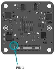
Type: Hirose DF40C-60DP-0.4V(51)#
Pinout |
Pinout |
Pinout |
Pinout |
||||
|---|---|---|---|---|---|---|---|
1 |
3V8_VDD |
16 |
RST_1 |
31 |
MCSSYNC |
46 |
D_DATA_3_P |
2 |
1V8_VDD |
17 |
NC |
32 |
FSTROBE |
47 |
NC |
3 |
3V8_VDD |
18 |
SDO |
33 |
PW_EN_0 |
48 |
D_DATA_3_N |
4 |
1V8_VDD |
19 |
NC |
34 |
PW_EN_1 |
49 |
GND |
5 |
NC |
20 |
TESTOUT |
35 |
SLAMODE0 |
50 |
GND |
6 |
NC |
21 |
I2C_SCL |
36 |
SLAMODE1 |
51 |
D_DATA_0_N |
7 |
NC |
22 |
SCK |
37 |
GND |
52 |
D_DATA_1_N |
8 |
NC |
23 |
SCSB |
38 |
GND |
53 |
D_DATA_0_P |
9 |
NC |
24 |
SLAMODE2 |
39 |
IS_MCLK_0 |
54 |
D_DATA_1_P |
10 |
NC |
25 |
XVS |
40 |
NC |
55 |
GND |
11 |
GND |
26 |
GPO |
41 |
NC |
56 |
GND |
12 |
GND |
27 |
I2C_SDA |
42 |
NC |
57 |
D_DATA_2_P |
13 |
GND |
28 |
SDI |
43 |
GND |
58 |
D_CLK_0_P |
14 |
GND |
29 |
NC |
44 |
GND |
59 |
D_DATA_2_N |
15 |
RST_0 |
30 |
NC |
45 |
NC |
60 |
D_CLK_0_N |
Note
PixelMate connectors use serpentine pin numbering as opposed to the standard numbering method.
Signal Description#
3V8_VDD I/O Type: Power Function: 3.8V Power supply Connected to: LDO_IC DC Charact.: 3V8_VDD=3.7V-5.1V, max. 0.3A per line |
1V8_VDD I/O Type: Power Function: 1.8V Power supply Connected to: LDO_IC DC Charact.: 1V8_VDD=1.7V-1.9V, max. 0.3A per line |
RST_0 / RST_1 I/O Type: IN Function: Image sensor reset (XCLR) Connected to: Reset_IC (RST_1 optional) I/O Standard: LVCMOS18 (1.8V) I/O State Normal: High, Reset: Low DC Charact.: VILmax=0.36V, VIHmin=1.44V |
SDO I/O Type: OUT Function: Gyro data output Connected to: Image Sensor I/O Standard: LVCMOS18 (1.8V) DC Charact.: VOLmax=0.36V, VOHmin=1.44V |
I2C_SCL I/O Type: IN/OUT Function: I2C clock Connected to: Image Sensor, pull-up resistor (not soldered) I/O Standard: LVCMOS18 (1.8V) DC Charact.: VILmax=0.54V, VIHmin=1.26V |
SCK I/O Type: OUT Function: Gyro control clock Connected to: Image Sensor I/O Standard: LVCMOS18 (1.8V) DC Charact.: VOLmax=0.36V, VOHmin=1.44V |
SCSB I/O Type: OUT Function: Gyro chip select Connected to: Image Sensor I/O Standard: LVCMOS18 (1.8V) DC Charact.: VOLmax=0.36V, VOHmin=1.44V |
SLAMODE2 I/O Type: IN/OUT Function: EEPROM I2C address configuration (A2) Connected to: EEPROM I/O Standard: LVCMOS18 (1.8V) DC Charact.: VILmax=0.36V, VIHmin=1.44V, VOLmax=0.2V, VOHmin=1.6V |
XVS I/O Type: IN/OUT Function: Image sensor frame synchronization Connected to: Image Sensor, pull-up resistor I/O Standard: LVCMOS18 (1.8V) DC Charact.: VILmax=0.36V, VIHmin=1.44V, VOLmax=0.2V, VOHmin=1.6V |
GPO I/O Type: OUT Function: Monitor signal output (configurable) Connected to: Image Sensor I/O Standard: LVCMOS18 (1.8V) DC Charact.: VOLmax=0.36V, VOHmin=1.44V |
I2C_SDA I/O Type: IN/OUT Function: I2C data Connected to: Image Sensor, pull-up resistor (not soldered) I/O Standard: LVCMOS18 (1.8V) DC Charact.: VILmax=0.36V, VIHmin=1.44V |
SDI I/O Type: IN/OUT Function: Gyro data input Connected to: Image Sensor I/O Standard: LVCMOS18 (1.8V) DC Charact.: VILmax=0.36V, VIHmin=1.44V, VOLmax=0.2V, VOHmin=1.6V |
MCSSYNC I/O Type: IN/OUT Function: Shutter trigger sync Connected to: Image Sensor I/O Standard: LVCMOS18 (1.8V) DC Charact.: VILmax=0.36V, VIHmin=1.44V, VOLmax=0.2V, VOHmin=1.6V |
FSTROBE I/O Type: OUT Function: Test output pin from image sensor Connected to: Image Sensor I/O Standard: LVCMOS18 (1.8V) DC Charact.: VOLmax=0.36V, VOHmin=1.44V |
PW_EN_0 / PW_EN_1 I/O Type: IN Function: Start of power-up sequence option Connected to: PW_Sequence_IC I/O Standard: LVCMOS18 (1.8V) I/O State Normal: High, PWR down: Low DC Charact.: VILmax=0.36V, VIHmin=1.44V |
SLAMODE0 / SLAMODE1 I/O Type: IN Function: Image sensor and EEPROM I2C slave address configuration Connected to: Image Sensor, pull up/down resistor I/O Standard: LVCMOS18 (1.8V) DC Charact.: VILmax=0.36V, VIHmin=1.44V |
IS_MCLK_0 I/O Type: IN CLK Function: Additional clock for image sensor from processing platform Connected to: Image Sensor I/O Standard: LVCMOS18 (1.8V) DC Charact.: VILmax=0.36V, VIHmin=1.44V |
TESTOUT I/O Type: OUT Function: Test output pin from image sensor Connected to: Image Sensor I/O Standard: LVCMOS18 (1.8V) |
D_DATA_1/2/3_P/N I/O Type: OUT Function: MIPI-CSI2 output data (Lane #, Positive/Negative) Connected to: Image Sensor I/O Standard: MIPI D-PHY |
D_CLK_0_P/N I/O Type: OUT Function: MIPI-CSI2 output clock (Lane 0, Positive/Negative) Connected to: Image Sensor I/O Standard: MIPI D-PHY |
I2C Address Configuration (SLAMODE)#
SLAMODE1 |
SLAMODE0 |
I2C Address |
|---|---|---|
0 |
0 |
0x1A |
0 |
1 |
0x10 |
1 |
0 |
0x36 |
1 |
1 |
0x37 |
Note
The FRAMOS driver uses the I2C Address 0x1A by default.
Users can configure additional SLAMODE signals via DIO (Digital Input/Output) pins from the host to set a different I2C Address.
When using multiple sensors on the same host, ensure each sensor is assigned a unique I2C Address to avoid conflicts.
Power-On Sequencing#
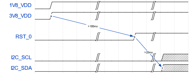
For correct function, the host system must follow the below timing to properly power up or reset the module.
3V8_VDD should be generated after 1V8_VDD, or, ideally at the same time. The RST_0 pin should be low after powering up PixelMate voltage rails; 180 ms.
Legend#
Times and voltages which are represented in the above figure are as follows:
3V8_VDD - 3V8 voltage supply from host
1V8_VDD - 1V8 voltage supply from host
RST_0 - reset signal driven from the host
I2C_SCL - I2C Clock
I2C_SDA - I2C Data
Mechanical Drawings#
Warning
Exercise caution when screwing the sensor in; the IMX06A has no flange to halt the screw. Screwing in carelessly may permanently damage the sensor.
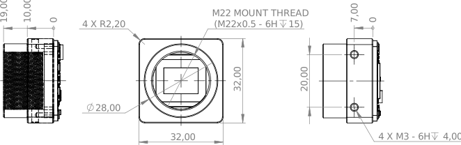
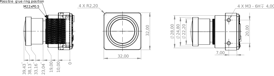
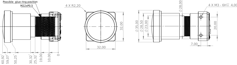
The following chapter contains measured drawings split into the core segments of the product.
Bare Sensor Module
with Lens
with Lens Mount only
All measures refer to the backside of the sensor module PCB and, this way, allow the acquisition of the overall measures. Units of measurement are expressed in milimeters [mm]² .
Sensor Module (Bare FSM:GO)#
Interface: PixelMate™#
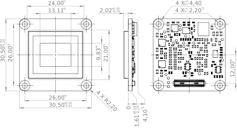
*1 - Clearance area
*2 - Hole size tolerance +/-0,1mm
*3 - Hole position tolerance +/-0,1mm
*4 - Connector size & alignment tolerance (X, Y, Z, tilt) +/-0,20mm
*5 - The center of the active sensor area is aligned with the center of the sensor board area
*5 - Sensor active area size & alignment tolerance (X, Y, Z, tilt) +/-0,25mm
2All mechanical components of the module assembly are subject to form and dimensional tolerances; therefore, sufficient mechanical clearance must be provided during integration, particularly around the lens and lens mount. The placement of electrical components on the PCBs (excluding connectors) may change without prior notice.
FSM:GO with Lens#
L81A: 81° HFOV (LH: M22A)#
L122A: 122° HFOV (LH: M22A)#
FSM:GO with Mount#
M22A: 19mm height#