
Multi Sensor Synchronization: SONY Global Shutter Sensors#
Introduction#
Global shutter sensors are designed to capture an image simultaneously across all pixels, eliminating motion artifacts typically associated with rolling shutter sensors. This feature is particularly beneficial in scenarios involving high-speed motion, such as industrial machine vision, robotics, and autonomous vehicles, where accurate and distortion-free imaging is critical.
Synchronization of global shutter sensor is a vital aspect of multi-camera systems, ensuring that all sensors capture images simultaneously. This document provides a comprehensive guide to synchronizing global shutter sensors in multi-sensor setups, explaining two primary methods of synchronization:
Using external signals,
Using sensor signals.
Global Shutter Sensor Overview#
Global shutter function enables simultaneous light integration across all pixels by utilizing pixel-level memory. Once the exposure is complete, the captured signal is transferred to pixel memory (a process known as memory transfer), ensuring all electrons are stored collectively.
The sensor features a variable electronic shutter function, allowing precise control over integration time units, facilitating flexible exposure adjustments. During the readout, the sensor sequentially outputs lines horizontally in sync with the XHS signal.
Additionally, the sensor supports trigger mode, enabling precise external control of timing the exposure via trigger signals. Check the sensor datasheet for more details (chapter: “Shutter and Integration Time Settings”).
SYNCHRONIZATION TECHNIQUES#
There are three modes of electronic shutter function control:
Normal Mode operation#
The exposure time is controlled by varying the electronic shutter timing. This is realized by adjusting the “SHS” register. In normal mode, the sensor can be operated as master or slave.
In master mode, the sensor uses internal timing signals defined by the registers. This mode does not require any external synchronization input and is typically used when the sensor operates independently or when it’s the primary timing source in a multi-camera system.
In slave mode, the sensor’s timings are driven by externally supplied synchronization signals (XVS, and XHS). In this configuration, the sensor aligns its exposure and readout to an external master device. The number of lines per frame is determined by the XVS interval, while the line duration is based on the XHS interval.
In multi-sensor systems with normal mode, synchronization is achieved by interconnecting the XVS and XHS signals between the sensors. All sensors in the system can be configured as slaves by providing both XVS and XHS signals from an external timing source. Alternatively, one sensor can be configured as the master and remaining sensors operate as slaves. The master will generate the XVS and XHS timing signals and slaves synchronized by following the timing of the master sensor.
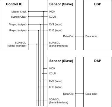
Figure 1: Synchronizing with external signals (all slave mode)
Figure 1 illustrates the sensor timing controlled by external signals (XVS and XHS). This setup allows for precise control over timing from an external source.
All image sensors operate in slave mode. Generation of XVS/XHS timing signals should be done to match timing constraints defined in the sensor datasheet (chapter:” XVS / XHS Input Characteristics in Slave Mode (XMASTER = High)”).
Typically, this is realized by utilizing microcontroller timer peripherals or using an FPGA. All sensors should use the same input clock to achieve best synchronization accuracy.
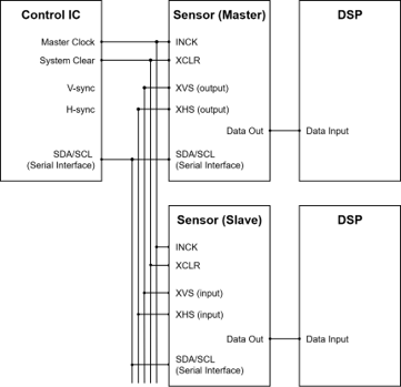
Figure 2: Synchronizing with sensor signals (one master and other slaves)
Figure 2 illustrates master-slave synchronization in normal mode operation. One sensor is configured as a master, generating XVS and XHS signals internally.
The frequency of generated XVS and XHS is determined by the VMAX and HMAX registers. This mode ensures multiple sensors can operate in sync without requiring external hardware.
All sensors should use the same input clock to achieve best synchronization accuracy.
Sequential Trigger Mode Operation#
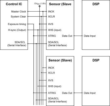
Figure 3: Synchronizing with external signals (all slave mode)
In Sequential Trigger Mode, all sensors operate in slave mode. The synchronization is achieved by providing external signals (XHS and XTRIG).
A falling edge on the XTRIG signal triggers the exposure start. The duration of the exposure time is defined by the XTRIG low-level time measured in XHS units.
Generation of XTRIG timing signals should be done to match timing constraints defined in the sensor datasheet (chapter: “XTRIG Input Characteristics in Slave Mode (XMASTER = High) only” and ”Parameter List of Global Shutters (Sequential Trigger Mode)”).
Fast Trigger Mode Operation#
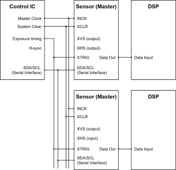
Figure 4: Synchronizing with external signals (all master mode)
In fast trigger mode, all sensors operate in master mode. The XVS and XHS pins must be left open since sensors use internal timing signals. This is an advantage over sequential trigger mode for some use cases, since less hardware signals are required.
Exposure starts immediately at the fall of XTRIG. This mode offers lower integration start/end delay comparing to sequential trigger mode, ensuring faster response time.
Generation of XTRIG timing signals should be done to match timing constraints defined in the sensor datasheet (chapter: “XTRIG Input Characteristics in Slave Mode (XMASTER = High) only” and “Parameter List of Global Shutter (Fast Trigger Mode)”).
All sensors should use the same input clock to achieve the best synchronization accuracy.
FSM ECOSYSTEM HARDWARE DESCRIPTION#
The aforementioned synchronization schemes require interconnecting the sensors sync signals (XVS or XHS or XTRIG) between the sensors to be synchronized. In addition, driving sensors in slave mode managing the sensor’s XMASTER pin is required. This chapter provides details on managing these signals in the FSM Ecosystem.
FPA-4.A/TXA#
Supported platforms: Jetson AGX Xavier, Jetson AGX Orin
The XVS and XHS signals can be managed on the board with a SW1 dip switch and the XTRIG signal with a SW2 dip switch.
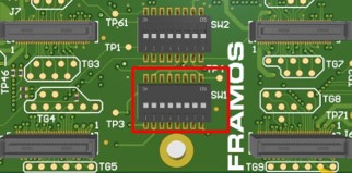
Figure 5: FPA-4.A/TXA; SW1 and SW2
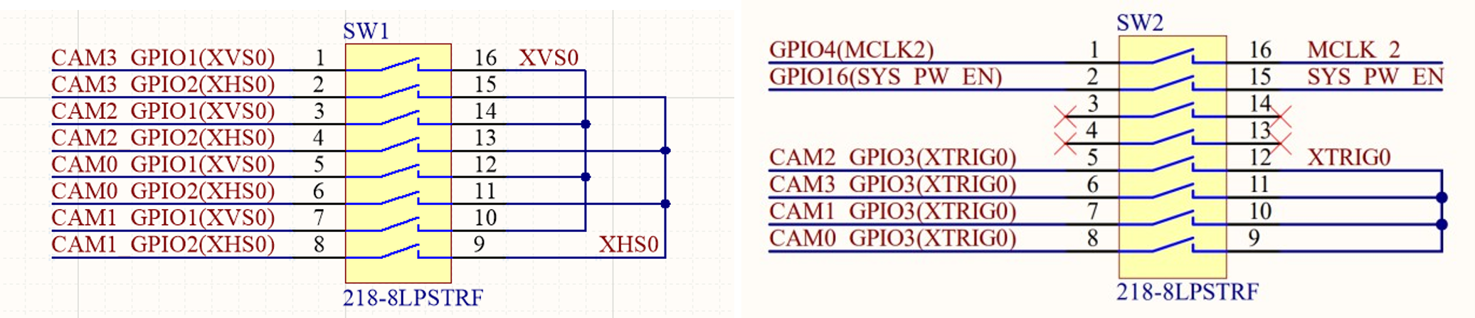
Figure 6: FPA-4.A/TXA schematics
With the FSM Ecosystem and FPA-4.A/TXA, it’s possible to synchronize up to 4 image sensors with standard FSA and FSM hardware. Image sensors can be connected to J5, J6, J7, and J8 connectors. An external XVS/XHS/XTRIG signal can be provided using J1.
FPA-4.A/AGX#
Supported platforms: Jetson AGX Xavier, Jetson AGX Orin
The sync signals (XVS /XHS/XTRIG) between the sensors connected to J5-J8 connectors can be interconnected using the respective XVS / XHS /XTRIG switches on the FPA. An external XVS/XHS/XTRIG signal can be provided using the J1 connector.
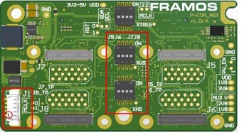
Figure 7: FPA-4.A/AGX; XHS, XVS and XTRIG
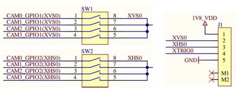
Figure 8: FPA-4.A/AGX Schematics
FPA-A/P22-V2A#
Supported platforms: Jetson Orin Nano & Orin NX
In FPA-A/P22-V2A, the XVS/XHS/XTRIG signals of different sensors can be connected by connecting the J4/J5 of one FPA to the J4/J5 of the other FPA.
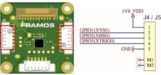
Figure 9: FPA-A/P22-V2A; J4/J5 Connectors
Slave Mode: FSM + FSA-FTx/A#
Sensors can be switched between slave and master mode using the XMASTER pin. The XMASTER pin is managed in the FSM development kit using FSA’s DIP-switch pin 4 (Figure 10). Other registers are communicated by the sensor driver using I2C.
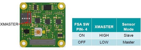
Figure 10: Sensor Mode Selection in FSA-FTx/A
Slave Mode: FSM: GO#
No DIP switch modifications are required for FSM:GO modules. The sensor’s XMASTER pin will be managed directly by the sensor driver using an I2C I/O expander located on the FPA.
EXAMPLE 1: MASTER-SLAVE SYNCHRONIZATION (NORMAL MODE)#
This chapter contains the hardware setup and software settings required to synchronize sensor modules in Master-Slave synchronizaton in the FSM ecosystem.
Prerequisites:#
FRAMOS Driver installed.
XMASTER pin enabled in the FSA for slave sensors. Only required for an FSM-FSA stacked setup.
Sensor modules connected to the Jetson platform using 60 pin PixelMate cables.
Hardware Setup: Jeston AGX Orin Platform#
Interconnect the XVS and XHS signals of the two sensors to be synchronized using the XVS and XHS switches in the FPA-4. A/AGX.
Example:
Figure 11 shows one FSM:GO-IMX900 connected to the J5 and another FSM:GO-IMX900 connected to the J7 connector of the FPA-A/AGX. The corresponding XVS & XHS signals are interconnected using the XVS and XHS switches in the FPA-4. A/AGX.
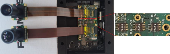
Figure 11: HW setup for master-slave sync in Jetson AGX Orin
Hardware Setup: Jetson Orin Nano Platform#
Interconnect the XVS and XHS signals between the sensors through the J4/J5 connectors on the FPA-A/P22-V2A.
Example:
Figure 12 shows one FSM:GO-IMX900 connected to CAM0 and another FSM:GO-IMX900 connected to CAM1 on the Jetson Orin Nano platform. The corresponding XVS & XHS signals are interconnected between the J4/J5 connectors on the FPA-A/P22-V2A using an FMA-CBL-MPB125-150/5 cable.
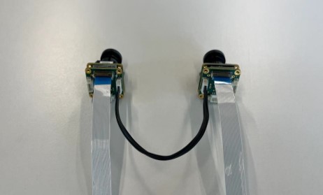
Figure 12: HW setup for master-slave sync in Jetson Orin Nano
Software Settings#
The image sensor’s operation mode and global shutter mode can be set using v4l controls. The control settings - operating mode and global shutter mode, should be modified as follows:
Control Setting |
Sensor 1 |
Sensor 2 |
|---|---|---|
Operation Mode |
0: Master Mode (default) |
1: Slave Mode |
Global Shutter mode |
0: Normal Mode (default) |
0: Normal Mode (Default) |
Table 1: Control Settings for Master-Slave Synchronization Mode
Note
These control settings are valid for drivers released for the AGX-Orin platform with driver package l4t-r36.4.3.
The v4l control settings can be modified using the prebuilt LibSV example - display_image or using the v4l2-ctl tool.
Using the LibSV display_image example to change driver settings (17, 20)
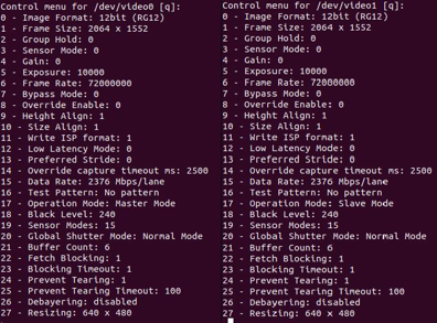
Figure 13: The Control Menu for the display_image LibSV example
Using the v4l2-ctl tool to change driver settings:
Sensor 1:
v4l2-ctl -d /dev/video0 -c "operation_mode=0" -c "global_shutter_mode=0"Sensor 2:
v4l2-ctl -d /dev/video1 -c "operation_mode=1" -c "global_shutter_mode=0"Using the v4l2-ctl tool to launch synchronized streams:
Terminal 1:
v4l2-ctl -d /dev/video0 --stream-mmap --stream-skip=10 --verboseTerminal 2:
v4l2-ctl -d /dev/video1 --stream-mmap --stream-skip=10 --verbose
EXAMPLE 2: SEQUENTIAL TRIGGER MODE#
This chapter explains the hardware setup and software settings required to synchronize the image sensors with an external trigger signal in sequential trigger mode. The external signal XTRIG can be generated using various sources (e.g. pulse generator, microcontroller, FPGA) considering the generated signal adheres to the electrical characteristics specified in the sensor documentation.
Prerequisites:#
FRAMOS driver installed.
XMASTER pin enabled in the FSA for all slave sensors. Only required for an FSM-FSA stacked setup.
Sensor modules connected to the Jetson platform.
The XTRIG signal and XHS signal provided using a function generator.

Figure 14: XTRIG/XHS signals generated using a function generator
XTRIG signals (CH1):
Frequency controls the FPS.
Duty controls duration of exposure time.
XHS signals (CH2):
Period calculated HMAX/INCK -> INCK = 74250000
Duty is set to max value
Hardware Setup: Jetson AGX Orin Platform#
Provide the external trigger signal and XHS to the J1 connector in the FPA-4.A/AGX. Enable XHS and XTRIG switches in FPA for multiple sensors to be synchronized. XVS is ignored in this mode. XVS can be interconnected to 1.8V.
Example:
Figure 15 shows one FSM:GO-IMX900 connected to the J5 and another FSM:GO-IMX900 connected to the J7 connectors of the FPA-A/AGX. The corresponding XHS, XTRIG signals are interconnected using the respective switches in the FPA-4.A/AGX. The external XHS and XTRIG signals are provided through the J1 connector using the FMA-CBL-MPB125-150/5 cable.
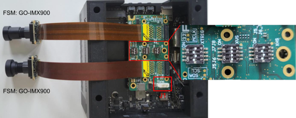
Figure 15: The HW setup for sequential trigger mode in AGX Orin
Hardware Setup: Jetson Orin Nano Platform#
Provide the XHS and XTRIG signals connecting an external signal to the J4/J5 connector and interconnect the sensors through the J5/J4 connector of the FPA-A/P22-V2A.
Example:
Figure 16 shows one FSM: GO-IMX900 connected to CAM0 and another FSM: GO-IMX900 connected to CAM1 on the Jetson Orin Nano platform. The corresponding XHS & XTRIG signals are interconnected using the J4/J5 connectors on the FPA-A/P22-V2A using the FMA-CBL-MPB125-150/5 cable.
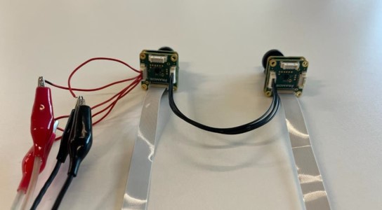
Figure 16: HW setup for sequential trigger mode on Jetson Orin Nano
Software Settings#
The image sensor’s operation mode and global shutter mode can be set using the v4l controls. The control settings - operating mode and global shutter mode, should be modified as follows:
Control Setting |
Sesnsor 1 |
Sensor 2 |
|---|---|---|
Operation mode |
1: Slave Mode |
1: Slave Mode |
Global Shutter mode |
1: Sequential Trigger Mode |
1: Sequential Trigger Mode |
Table 2: Control Settings for Sequential Trigger Mode
Note
These control settings are valid for drivers released for AGX-Orin platform with driver package l4t-r36.4.3.
The v4l control settings can be modified using the prebuilt LibSV example - display_image or using the v4l2-ctl tool.
Using the LibSV display_image example to change driver settings (17,20). Change the operation mode first, and then the shutter mode.
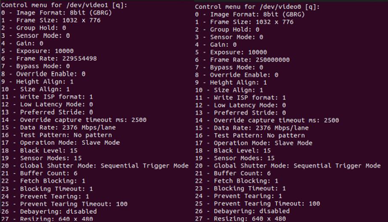
Figure 17: The Control Menu for the display_image LibSV example
Using the v4l2-ctl tool to change driver settings:
Sensor 1:
v4l2-ctl -d /dev/video0 -c "operation_mode=1" -c "global_shutter_mode=1"Sensor 2:
v4l2-ctl -d /dev/video1 -c "operation_mode=1" -c "global_shutter_mode=1"Using the v4l2-ctl tool to launch synchronized streams:
Terminal 1:
v4l2-ctl -d /dev/video0 --stream-mmap --stream-skip=10 --verboseTerminal 2:
v4l2-ctl -d /dev/video1 --stream-mmap --stream-skip=10 --verbose
Note
Launch the streams and then turn on external sync signals.
EXAMPLE 3: FAST TRIGGER MODE#
This chapter explains the hardware setup and software settings required to synchronize the image sensors with an external trigger signal in fast trigger mode. The external signal XTRIG can be generated using various sources (e.g. pulse generator, microcontroller, FPGA) considering the generated signal adheres to the electrical characteristics specified in the sensor documentation.
Prerequisites:#
FRAMOS driver installed
Sensor modules connected to the Jetson platform.
XTRIG signal provided through function generator.
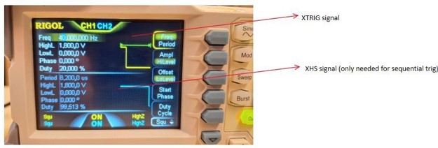
Figure 18: XTRIG signals generated using a function generator
XTRIG signals (CH1):
Frequency controls the FPS.
Duty controls exposure timing.
Hardware Setup: Jetson AGX Orin Platform#
Provide the external trigger signal to the J1 connector in the FPA-4.A/AGX. The XVS and XHS inputs are kept open. Enable the XTRIG switches for interconnecting trigger signals between the sensors.
Example:
Figure 19 shows one FSM:GO-IMX900 connected to the J5 and other FSM:GO-IMX900 connected to the J7 connectors of the FPA-A/AGX. The XTRIG signal is input through the J1 connector using the FMA-CBL-MPB125-150/5 cable. The corresponding XTRIG signals are interconnected using the respective switches in the FPA-4.A/AGX.
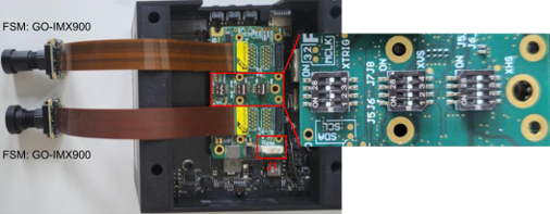
Figure 19: HW setup for fast trigger mode on Jetson AGX Orin
Hardware Setup: Jetson Orin Nano Platform#
Provide the XTRIG signal connecting an external signal to the J4/J5 connector, interconnect the sensors through the J5/J4 connector of the FPA-A/P22-V2A.
Example:
Connect one FSM:GO-IMX900 to CAM0 and another FSM:GO-IMX900 to CAM1 on the Jetson Orin Nano platform. The corresponding XTRIG signal is interconnected using the J4/J5 connectors on the FPA-A/P22-V2A and a cable. Refer to Figure 16.
Software Settings#
The image sensor’s operation mode and global shutter mode can be set using the v4l controls. The control settings - operating mode aend global shutter mode should be modified as follows:
Control Setting |
Sensor 1 |
Sensor 2 |
|---|---|---|
Operation Mode |
1: Master Mode |
1: Master Mode |
Global Shutter Mode |
1: Fast Trigger Mode |
1: Fast Trigger Mode |
Table 3: Control Settings for Sequential Trigger Mode
Note
These control settings are valid for drivers released for the AGX-Orin platform with driver package l4t-r36.4.3.
The v4l control settings can be modified using the prebuilt LibSV example - display_image or using the v4l2-ctl tool.
Using the LibSV display_image example to change driver settings (17, 20), change the operation mode first, then the shutter mode.
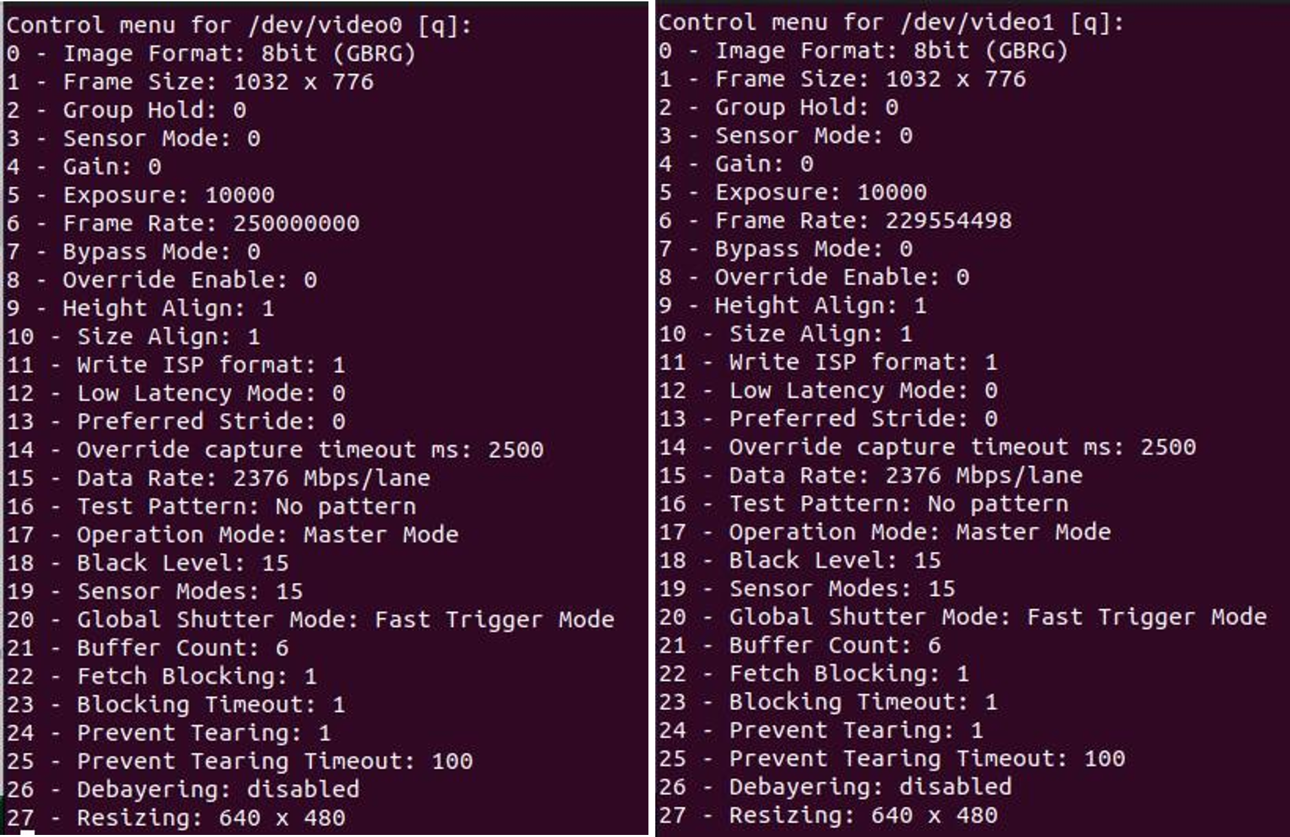
Figure 20: The Control Menu For the display_image LibSV example
Using the v4l2-ctl tool to change driver settings:
Sensor 1:
v4l2-ctl -d /dev/video0 -c "operation_mode=0" -c "global_shutter_mode=2"Sensor 2:
v4l2-ctl -d /dev/video1 -c "operation_mode=0" -c "global_shutter_mode=2"Using the v4l2-ctl tool to launch synchronized streams:
Terminal 1:
v4l2-ctl -d /dev/video0 --stream-mmap --stream-skip=10 --verboseTerminal 2:
v4l2-ctl -d /dev/video1 --stream-mmap --stream-skip=10 --verbose
Note
Launch the streams and then turn on external sync signals.
REFERENCES#
APPENDIX#
Supported Sensors
IMX296/297
IMX900